
Power Distribution and Grounding for Telecommunications Infrastructure
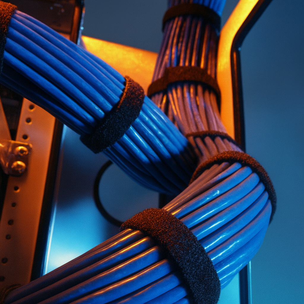
The reliable operation of a new build's telecommunications infrastructure hinges critically on adequately designed and implemented power distribution and grounding systems. This extends beyond basic electrical outlets to dedicated circuits, uninterruptible power supplies (UPS), and robust grounding and bonding networks specified by ANSI/TIA-607-C. We collaborate closely with electrical engineers to ensure that telecommunications rooms (TRs), equipment racks, and data centers are supplied with sufficient dedicated power circuits, often on separate panels, to prevent interference and ensure stability. This includes specifying appropriate voltage (e.g., 120V, 208V), amperage, and NEMA receptacle types for active equipment. UPS systems are often integrated to provide battery backup for critical network devices, ensuring continuity of service during power fluctuations or outages. Our scope involves coordinating the installation of dedicated electrical panels, distribution units (PDUs) within racks, and surge protection devices. Crucially, a comprehensive grounding and bonding infrastructure is implemented throughout the cabling system. All metallic components, including racks, cabinets, cable trays, conduits, and equipment frames, are bonded to the Telecommunications Main Grounding Busbar (TMGB) or Telecommunications Grounding Busbar (TGB) via properly sized grounding conductors (e.g., AWG #6, #2) and listed bonding hardware. This prevents ground loops, reduces electromagnetic interference (EMI), and provides a safe path for fault currents, protecting both personnel and valuable equipment. Non-compliance with TIA-607-C grounding standards can lead to intermittent network issues, equipment damage, warranty voidance, and significant safety hazards. We utilize precision ohmmeters and ground resistance testers to verify the integrity and effectiveness of the installed grounding system, delivering detailed test reports as part of the final documentation package. Careful consideration is also given to the separation of power and data cabling during cable tray and conduit installation to minimize cross-talk and induction, following industry best practices for cable management.
Why Torrance teams choose Access Cabling for new construction cabling
Across Torrance — from Del Amo Fashion to the surrounding Los Angeles County corridor — IT directors and facilities managers pick Access Cabling for the same reasons: a licensed C-10 / C-7 contractor (CSLB 992009), 28+ years of commercial projects experience, BICSI-trained crews on-site, and Fluke DSX certification on every port. The result is a new construction cabling install that a network engineer can drop into on day one — labeled, tested, and warranted for 25 years.
Navigating Torrance Permitting & Building Regulations
Undertaking commercial cabling projects in Torrance requires a thorough understanding of local permitting and inspection processes to ensure compliance and timely completion. The City of Torrance Community Development Department, specifically the Building and Safety Division, oversees low-voltage permits. Our team is adept at navigating these requirements, from preparing detailed scope-of-work documentation to coordinating inspections for various commercial building types common in Torrance, such as tilt-up warehouses, Class A office parks, and mixed-use developments. We ensure all installations adhere to the California Electrical Code (CEC) and local ordinances, minimizing delays and ensuring that projects are permitted correctly from conception to final sign-off, which is crucial for businesses operating within Torrance and Los Angeles County.
Testing, Certification, and Documentation to TIA Standards
Post-installation, Access Cabling performs rigorous testing and certification of every cable run to validate performance against TIA/EIA standards. We utilize industry-leading test equipment, such as the Fluke DSX CableAnalyzer series, to conduct comprehensive tests including insertion loss, return loss, near-end crosstalk (NEXT), far-end crosstalk (FEXT), propagation delay, and wire map. For fiber optic cabling, we perform OTDR (Optical Time Domain Reflectometer) and OLTS (Optical Loss Test Set) tests to measure insertion loss, optical return loss, and identify any anomalies or breaks. All test results are compiled into detailed certification reports, providing verifiable proof that the installed infrastructure meets or exceeds Category 6A, OS2, or OM4 performance specifications. This documentation is critical for client acceptance, warranty validation, and serves as a baseline for future network diagnostics and upgrades, ensuring the network performs as expected from day one.