Reliable, high-bandwidth data transmission is critical for modern commercial operations, and fiber optic cabling remains the gold standard. For IT directors, facilities managers, and general contractors overseeing infrastructure projects, the precise installation, termination, and testing of fiber optic systems are non-negotiable for ensuring network performance and longevity. Access Cabling specializes in delivering robust single-mode and multimode fiber optic installations that adhere rigorously to TIA/EIA, BICSI, and NEC standards. Our approach integrates meticulous design, manufacturer-certified components from partners like Corning and Panduit, and Fluke DSX testing methodologies, all executed by C-10/C-7 licensed technicians. We understand that fiber infrastructure isn't just about speed; it's about future-proofing your network against increasing data demands and ensuring operational continuity. We provide a guaranteed, documented fiber optic installation that functions optimally from day one, backed by 28+ years of specialized experience.
Fiber Optic Overview: Standards and Core Principles
Fiber optic installation encompasses the structured deployment of glass or plastic strands to transmit light-encoded data, offering significantly higher bandwidth, longer transmission distances, and greater immunity to electromagnetic interference (EMI) than copper cabling. Our installations strictly adhere to industry standards including TIA-568 (Commercial Building Telecommunications Cabling Standard), TIA-569 (Telecommunications Pathways and Spaces), and TIA-606 (Administration Standard for Telecommunications Infrastructure). The National Electrical Code (NEC) Article 770 specifically governs optical fiber cables, addressing fire ratings (e.g., OFNP, OFNR) and safe installation practices within buildings. Core principles revolve around minimizing attenuation and dispersion through proper cable handling, fusion splicing (for single-mode) or mechanical termination (for multimode), and maintaining appropriate bend radii to prevent signal loss. Multimode fiber (OM1, OM2, OM3, OM4, OM5) is generally used for shorter distances within buildings and campuses, while single-mode fiber (OS1, OS2) is preferred for long-haul runs and high-speed applications due to its significantly larger bandwidth and distance capabilities.
Optical Fiber System Design and Engineering Considerations
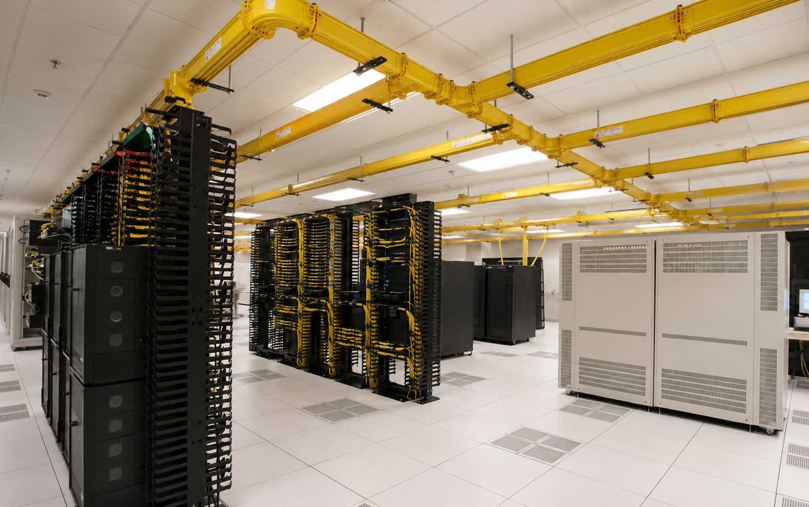
Effective fiber optic system design starts with a comprehensive needs analysis, considering current and projected bandwidth requirements, transmission distances, environmental factors, and budget constraints. Our engineers assess cable routes for potential hazards, pathway capacities, and fire resistance ratings required per NEC. We determine the appropriate fiber type (OS2, OM4, OM5), core count, and cabling construction (e.g., tight-buffered, loose-tube, armored) for the specific application. Link loss budgets are meticulously calculated, accounting for cable attenuation, connector losses, and splice losses, to ensure end-to-end signal integrity. This includes evaluating the use of pre-terminated assemblies versus field termination, designing for future scalability, and specifying adequate slack for re-terminations or moves/adds/changes. For data center environments, optimizing structured cabling pathways and cabinet layouts for high-density fiber becomes critical, often leveraging MPO/MTP connectors and pre-engineered backbone systems to minimize installation time and maximize efficiency. Each design is documented with detailed schematics and rack elevations before deployment.
Critical Components: Fiber Optic Cable and Connectivity Hardware
The choice of fiber optic cable and connectivity components significantly impacts network performance and longevity. We utilize tier-one manufacturer products from industry leaders such as Corning, Panduit, CommScope, Leviton, and Belden. For multimode installations, we commonly deploy OM3 (50/125µm), OM4, or OM5 wide-band multimode fiber (WBMMF) cables, supporting 10/40/100 Gigabit Ethernet over various distances as defined by IEEE 802.3 standards. Single-mode deployments feature OS2 (9/125µm) cables, suitable for long-distance, high-bandwidth applications up to 400G and beyond. Connectors, critical for mating fiber ends, are carefully selected based on application; common types include LC (Lucent Connector) for small form factor and high-density patching, SC (Standard Connector) for general campus backbones, and MPO/MTP (Multi-fiber Push-on/pull-off) for high-density multi-fiber connections, particularly in data centers. Patch panels, enclosures, splice trays, and breakout cassettes are specified to provide proper fiber management, protection, and accessibility, ensuring optimal bend radius control and strain relief for all cable runs. All components are chosen for their compatibility and performance characteristics within the designed optical link.
Precision Installation and Termination Methodologies
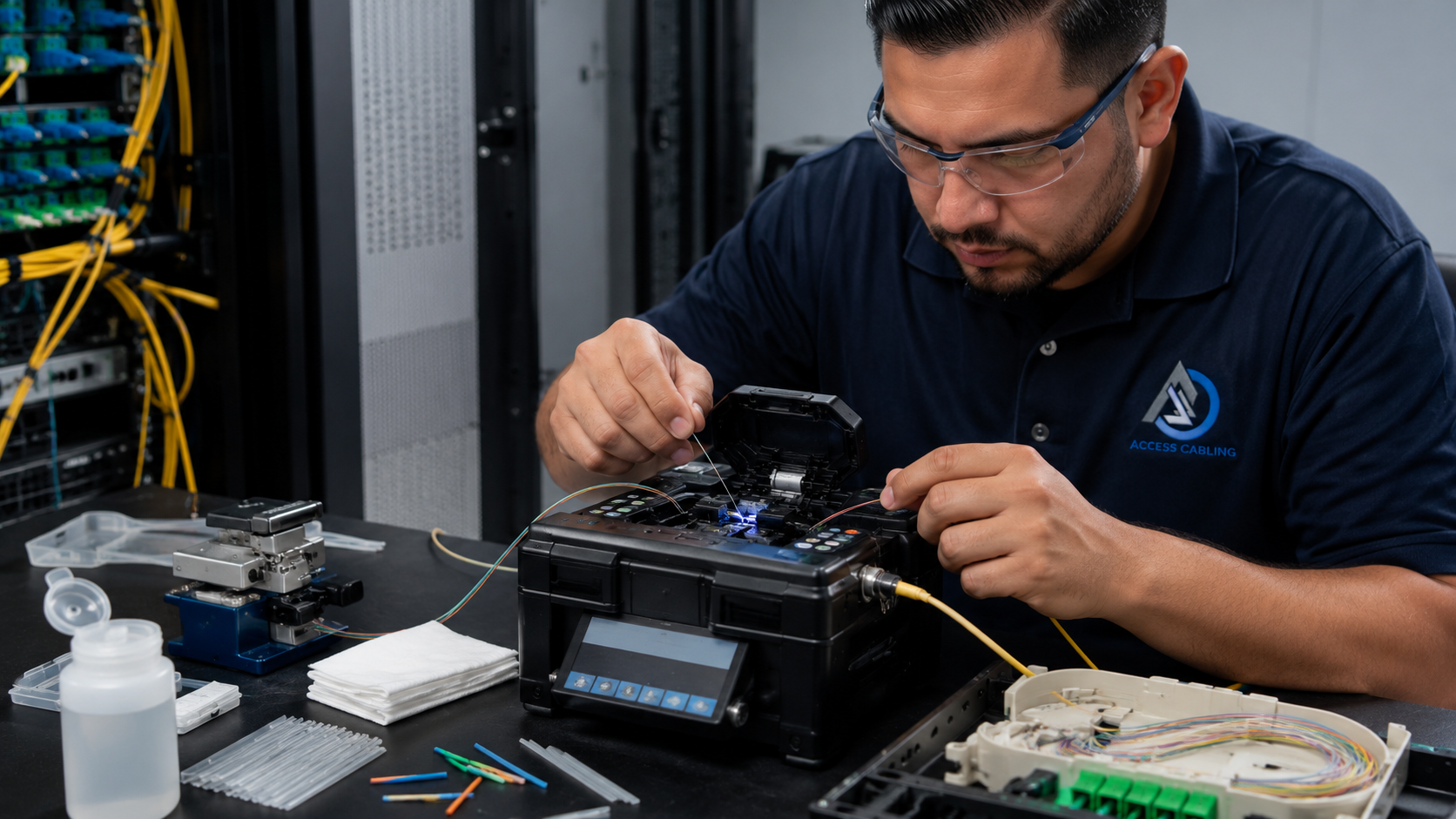
Our installation process for fiber optic cabling is executed with precision, adhering to manufacturer guidelines and BICSI best practices. Cable pulling techniques are rigorously controlled to prevent exceeding maximum tensile loading and maintaining minimum bend radii throughout the entire pathway. For termination, single-mode fiber often requires fusion splicing using specialized equipment like Furukawa or Sumitomo fusion splicers, creating low-loss, permanent connections that are subsequently protected within splice trays. Multimode fiber can be terminated via fusion splicing or mechanical connectors (e.g., Unicam connectors), with the choice depending on application, loss budget, and environment. We frequently employ pre-terminated fiber assemblies for data center links to reduce field termination time and ensure factory-guaranteed performance. All field terminations, whether splice-on or epoxy-polish, are performed by certified technicians using cleanroom protocols to prevent contamination, which can severely degrade optical performance. Proper slack management, labeling (per TIA-606-C), and pathway organization are integrated from the initial stages to facilitate future maintenance and troubleshooting.
Comprehensive Fiber Optic Testing and Certification
Testing and certification are non-negotiable steps in every fiber optic installation, providing empirical evidence of performance and guaranteeing adherence to TIA standards. We utilize advanced optical time-domain reflectometers (OTDRs) like the Fluke DSX-8000 and OFP-200 and optical loss test sets (OLTS) for Tier 1 and Tier 2 certification. Tier 1 testing, also known as Basic Link Loss measurement (per TIA-568.3-E), measures the total insertion loss of a fiber link with a light source and power meter, characterizing the overall attenuation. Tier 2 testing adds OTDR analysis, providing a graphical trace of the fiber link, identifying and localizing events such as splices, connectors, and breaks, and measuring their individual reflectivity and attenuation. Additionally, end-face inspection using a microscope (e.g., Fluke FI-7000 or FI-1000) is performed on all terminated connectors to ensure compliance with IEC 61300-3-35 cleanliness standards. This comprehensive testing suite generates detailed pass/fail reports, providing a performance baseline and warranty documentation for the client's infrastructure.
Key Applications and Use Cases for Fiber Optic Networks
Fiber optic networks are foundational to a wide array of commercial and industrial applications, capitalizing on their superior bandwidth, distance, and immunity to interference. In data centers, fiber is indispensable for high-speed backbone connections between servers, storage area networks (SANs), and network switches, supporting 10/40/100/400 Gigabit Ethernet and Fibre Channel protocols. For campus environments, fiber provides the inter-building connectivity, linking disparate facilities across significant distances with minimal signal degradation. In industrial settings, fiber's immunity to EMI and RFI makes it ideal for networks deployed near heavy machinery, high-voltage equipment, or in harsh environmental conditions. Critical infrastructure, including hospitals, financial institutions, and government facilities, relies on fiber for secure, reliable, and high-capacity data transmission. Furthermore, fiber-to-the-desk (FTTD) solutions are gaining traction for niche applications requiring maximum security and bandwidth to individual workstations, illustrating the versatility and expanding relevance of fiber optic cabling across virtually all sectors requiring robust network infrastructure.
Regulatory Compliance, Safety, and Guaranteed Implementation
Compliance with regulatory standards and stringent safety protocols is paramount in all fiber optic installations. Beyond TIA/EIA and BICSI guidelines, all work strictly adheres to the National Electrical Code (NEC Article 770) concerning cable fire ratings (e.g., plenum-rated OFNP, riser-rated OFNR), grounding, and bonding requirements specific to optical fiber. Our C-10/C-7 licensed technicians are trained in critical safety practices, including proper handling of fusion splicers (which generate intense heat) and the use of personal protective equipment (PPE) to guard against laser radiation exposure, especially when working with live fiber. Confined space entry procedures, lock-out/tag-out (LOTO) protocols, and fall protection are implemented as required by OSHA regulations. Access Cabling's 28+ years of experience ensures that every fiber optic installation not only meets but exceeds industry performance benchmarks, providing a documented, certified, and fully warranted solution. Our commitment to quality, safety, and adherence to all governing codes minimizes risk and ensures the long-term reliability of your critical network infrastructure.
Streamlining Fiber Optic Project Management & Logistics
Effective fiber optic network deployment necessitates a rigorous project management framework that extends far beyond the physical installation. Our approach integrates PRINCE2 and PMBOK methodologies, adapted specifically for telecommunications infrastructure. This includes meticulous resource allocation, critical path analysis to identify and mitigate schedule dependencies, and real-time risk assessment, particularly pertinent in brownfield deployments or where strict uptime SLAs exist. Coordination with other trades, such as Mechanical, Electrical, and Plumbing (MEP), is paramount to prevent clashes and ensure proper conduit fill ratios as per TIA-569-C and BICSI standards. For instance, avoiding proximity to high-voltage lines or sources of electromagnetic interference (EMI) is critical. We utilize BIM (Building Information Modeling) and CAD overlay systems to preemptively identify potential conflicts between fiber pathways and existing or planned building systems, thereby reducing costly rework and delays during the construction phase. Logistics management involves not just procurement of industry-leading Corning, CommScope, or AFL fiber and passive optical network (PON) components, but also just-in-time delivery strategies to minimize on-site storage requirements and prevent material degradation or theft. This includes detailed tracking of specialized equipment such as fusion splicers (e.g., Fujikura 90S or Sumitomo Type-72C+), OTDRs (e.g., EXFO FTB-1 Pro or Viavi MTS-4000), and fiber microscopes, ensuring their immediate availability for installation and troubleshooting phases. Adherence to project timelines is maintained through agile sprints for modular deployments and daily stand-ups with all stakeholders, including facility managers and IT department leads, fostering transparent communication and swift resolution of emergent issues. Our comprehensive project close-out procedures include as-built documentation, operational readiness reviews, and knowledge transfer sessions to client personnel, ensuring long-term operational success.
Fiber Network Security, Redundancy, and Disaster Recovery Planning
The inherent security and robust performance of fiber optic networks are key drivers for adoption, but their full potential is realized only through deliberate architectural planning for redundancy and disaster recovery. Physical security of the fiber plant, from outside plant (OSP) armored cables to inside plant (ISP) pathways, is paramount. This involves specifying conduit systems (e.g., HDPE, galvanized steel) with appropriate burial depths or fire-rated pathways (e.g., UL 2024 compliant) to deter unauthorized access and protect against environmental hazards. Monitoring systems, such as Distributed Acoustic Sensing (DAS) on the fiber itself, can detect intrusions or unauthorized digging attempts. Logical security within the network layer, while not directly a fiber installation topic, is heavily influenced by the physical topology. We design networks utilizing diverse routing strategies, ensuring that critical data paths traverse geographically separate routes to avoid single points of failure. For example, a ring topology provides inherent resilience, allowing data redirection in case of a cable cut. Implementing dark fiber solutions offers superior control and security, as the physical layer is dedicated to the client, preventing potential eavesdropping or passive optical tapping that can sometimes occur in shared infrastructure environments if not properly managed. Disaster recovery planning integrates seamlessly with network redundancy. This involves pre-planned emergency restoral procedures, including readily accessible spare fiber spools, pre-connectorized patch panels, and mobile fusion splicing units. Our designs often incorporate hardened network operation centers (NOCs) and secondary data centers connected via multiple, physically diverse fiber links, engineered to withstand various environmental and man-made threats. This proactive approach ensures business continuity and minimizes recovery time objectives (RTO) and recovery point objectives (RPO) in the event of unforeseen outages, going beyond mere cable installation to secure the data flow itself.
Advanced OSP Deployment: Trenching, Directional Boring, and Aerial Solutions
Outside Plant (OSP) fiber optic deployment presents a unique set of engineering and logistical challenges, requiring specialized methodologies for varied terrains and urban environments. Our expertise encompasses a full spectrum of OSP techniques, including traditional open trenching, horizontal directional drilling (HDD), and aerial construction. Open trenching, regulated by local municipal codes for depth and backfill specifications (e.g., ASTM F645 for conduit installation), is employed in less congested areas. This involves meticulous soil analysis, utility locating (e.g., using GPR and EM induction devices as per ASCE 38-02), and precise excavation to lay conduit or direct-bury fiber optic cables (e.g., AFL OSP Multi-Loose Tube, Corning SST-Drop). For traverses beneath rivers, roads, or existing infrastructure, HDD, complying with ASTM F1962 for trenchless technologies, is the preferred method. This requires bore path planning, fluid management (bentonite slurry), and the use of specialized drilling rigs and locators (e.g., Ditch Witch JT series or Vermeer D-series), ensuring minimal surface disruption and adherence to pipe-pulling forces to prevent microbending and macrobending losses. Aerial fiber deployment, often leveraging existing utility poles, adheres strictly to NESC (National Electrical Safety Code) clearances and pole loading standards (e.g., ANSI O5.1). This involves careful pole-attachment agreements, strand lashing techniques, and the use of ADSS (All-Dielectric Self-Supporting) or figure-8 self-supporting cables (e.g., CommScope ALTOS® ADSS, Prysmian Flextube®) chosen for their tensile strength and wind loading characteristics. Each method necessitates precise site surveys, environmental impact assessments, and adherence to local permitting requirements, ensuring long-term reliability and minimizing future maintenance liabilities, with careful consideration of rodent and pest protection for direct-bury and aerial installations.
Long-Term Network Evolution: Scalability, Upgrade Paths, and TCO Optimization
Designing a fiber optic network requires a forward-thinking perspective, prioritizing scalability and identifying clear upgrade paths to future-proof the infrastructure against evolving technological demands and increasing bandwidth consumption. Our installations are executed with a keen eye on the total cost of ownership (TCO), not just initial CAPEX. This involves selecting fiber types that support future generations of optical transmission, such as G.657.A2 bend-insensitive single-mode fiber for data center interconnects or FTTH deployments, offering superior performance and flexibility compared to older G.652.D. We recommend conduit systems with sufficient spare capacity – typically 25-50% empty duct space – to accommodate additional fiber runs without costly re-excavation or re-stringing. Modular patch panels and distribution frames (e.g., OFDF, LGX-compatible systems) are always specified, enabling seamless expansion with minimal service disruption. Active equipment spaces, such as communication closets and data centers, are designed with adequate power, cooling, and rack unit (RU) availability to support future optical transceivers (e.g., 100G, 400G, 800G QSFP-DD) and CWDM/DWDM multiplexers. Our documentation deliverables include detailed future-state diagrams projecting network capabilities five to ten years out, outlining potential technology refreshes (e.g., migration from 10G PON to XGS-PON or 25G PON) and associated cost implications. By integrating robust cable management, intelligent fiber routing, and strategic placement of splicing points and access chambers, we minimize the operational expenditure (OPEX) associated with moves, adds, and changes (MACs). This holistic approach to network design and installation ensures that the fiber infrastructure remains an asset that can adapt and grow with the business, delaying costly complete overhauls and optimizing long-term ROI.