Access Cabling commercial structured cabling infrastructure
Commercial · Fiber

Fiber Testing Services

OTDR, insertion loss and end-face inspection for every strand.

28+ Years Experience
C-10 / C-7 Contractor
CSLB: 992009
Licensed Commercial Contractor
5 California Offices
California & Nationwide Service

Request a Fiber Testing site survey

Free, no-obligation walkthrough. Licensed C-10 / C-7 (CSLB #992009). 28+ years, California & nationwide.

Request a site survey
Commercial Service Overview

Enterprise-grade fiber testing engineered for commercial buildings.

Fiber Testing from Access Cabling delivers enterprise-grade fiber testing engineered by a licensed low-voltage contractor with 28+ years serving California and nationwide clients. Our BICSI-trained technicians design, install, terminate, test and certify every run to TIA/EIA standards so your infrastructure supports current bandwidth demands and future growth.

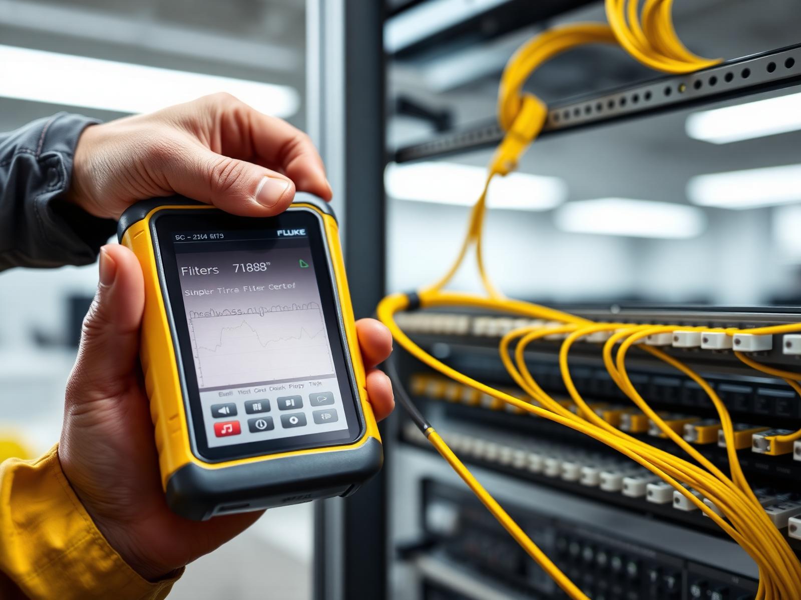
Technician holding a yellow Fluke-style fiber certifier connected to a fiber patch panel with LC connectors.
Key Benefits

Why fiber testing from Access Cabling

Commercial-grade installation, certified performance, and infrastructure built to last 25+ years.

Certified installation by BICSI-trained technicians
Manufacturer warranties up to 25 years on structured cabling
Fluke DSX certification reports on every project
Licensed C-10 / C-7 low-voltage contractor
24/7 emergency response and MAC services
Nationwide coverage with California headquarters
Installation Process

Our proven commercial cabling process

A repeatable, engineered process — refined over 28 years and thousands of sites.

  1. Step 1

    Free on-site survey and needs assessment

  2. Step 2

    Engineered design with rack elevations and pathway plans

  3. Step 3

    Scheduled installation with minimal business disruption

  4. Step 4

    Termination, testing, labeling and documentation

  5. Step 5

    Fluke certification and as-built drawings delivered

Technical Standards & Testing

TIA-compliant. Fluke-certified. Fully documented.

Every fiber testing installation follows TIA-568, TIA-606 labeling, NEC 800 and applicable manufacturer specifications. Fluke DSX Versiv certification and full as-built documentation are delivered at project close.

  • TIA-568 structured cabling standards
  • TIA-606 labeling and administration
  • TIA-942 data center infrastructure
  • Fluke DSX-8000 channel and link certification
  • Manufacturer certified installer for Panduit, CommScope, Leviton
Access Cabling commercial structured cabling infrastructure
Industries Served

Fiber Testing for every commercial environment

28+
Years
5
CA Offices
50
States
12M+
Feet Installed
Local Service Area

Fiber Testing across California & nationwide

Local crews dispatched daily from five California offices. Multi-site rollouts across all 50 states.

In Depth

A closer look at fiber testing

Accurate fiber optic testing is not merely a procedural step; it is the cornerstone of network reliability and performance, directly impacting an enterprise's operational continuity and ROI. As optical fiber increasingly forms the backbone of critical commercial infrastructures, from data centers and hyperscale networks to intelligent buildings and industrial automation, ensuring its integrity from the initial deployment through its operational lifecycle is paramount. Access Cabling specializes in comprehensive fiber optic testing, leveraging advanced methodologies and TIA/EIA-compliant practices to validate every strand. Our Certified Fiber Optic Technicians (CFOTs) utilize precision equipment, including Optical Time Domain Reflectometers (OTDRs), insertion loss testers, and digital fiber end-face microscopes, to provide verifiable, granular data on link performance. We go beyond basic pass/fail reporting, delivering a detailed analytical assessment that mitigates future issues, optimizes network efficiency, and guarantees adherence to stringent industry standards. Our approach ensures that your fiber plant not only meets but exceeds performance expectations, backed by documentation that provides a clear audit trail for compliance and troubleshooting.

Comprehensive Fiber Optic Testing Methodologies and Standards

Fiber optic testing encompasses a suite of procedures designed to characterize the performance and physical integrity of optical cables and components. Access Cabling adheres strictly to TIA-568.3-E and ISO/IEC 11801 standards, which dictate testing parameters for multimode and single-mode fiber infrastructure. Our Level 1 testing, also known as Tier 1 or Basic Link testing, involves measuring insertion loss using a calibrated light source and power meter (LSPM) at specified wavelengths (e.g., 850nm and 1300nm for multimode, 1310nm and 1550nm for single-mode). This directly assesses the total attenuation of the optical path, including connectors, splices, and the fiber itself. We perform bidirectional testing to average loss values, negating power variations at different ends of the link, as recommended by ANSI/TIA-526-14-B for multimode and ANSI/TIA-526-7-B for single-mode. This foundational testing provides critical data for establishing baseline performance and verifying compliance with application-specific loss budgets.

Advanced OTDR Testing for Fiber Optic Link Characterization (Tier 2/Extended)

Building upon Level 1 measurements, Access Cabling provides Level 2 (Tier 2 or Extended) testing using Optical Time Domain Reflectometers (OTDRs). An OTDR injects high-powered optical pulses into the fiber and measures the reflected light (backscatter) and Fresnel reflections from discrete events like connectors, splices, and faults. This allows for precise event mapping, identification of loss events, and measurement of reflectance. We utilize advanced OTDRs from manufacturers like Fluke Networks (e.g., OptiFiber Pro series) or Anritsu, configured with appropriate launch and receive cables to ensure accurate characterization of the first and last connectors. Data gathered includes attenuation per kilometer, event loss (dB), event reflectance (dB), and overall link length, all presented in graphical trace form with pass/fail analysis customizable to TIA-568 or application-specific limits. OTDR traces are critical for diagnosing elusive problems and pinpointing fault locations to within meters in long-haul links, single-mode fiber deployments, or complex campus backbone environments where accurate characterization is essential for future upgrades and troubleshooting.

Critical Importance of Fiber End-Face Inspection

Fiber end-face inspection is arguably the most critical step in ensuring optimal optical performance and preventing future issues, yet it is often overlooked. Contamination or damage on connector end-faces is the leading cause of signal loss, back reflection, and network instability. Access Cabling follows the IEC 61300-3-35 standard, which specifies acceptance criteria for fiber optic connector end-face quality for various fiber types (multimode, single-mode, PC, APC, MPO). We utilize calibrated digital fiber inspection microscopes, such as those from EXFO (e.g., FiberInspector Max) or Viavi, capable of 200x or 400x magnification. Every connector end-face being installed, mated, or re-mated is inspected and cleaned if necessary, prior to any testing. This meticulous process ensures that no microscopic dust, oil, or scratches introduce excessive insertion loss or reflectance, which can cause intermittent faults, premature equipment failure, and degraded network throughput. Automated analysis software within these microscopes provides objective pass/fail results, eliminating subjective interpretation and guaranteeing consistent quality across all terminations.

Design Considerations for Test Access Points and Future Scalability

Effective fiber testing begins long before any light is injected into the cable. During the design phase, Access Cabling collaborates with IT departments and network architects to implement strategies that facilitate efficient and accurate testing throughout the fiber plant's lifecycle. This includes considerations for accessible splice points, appropriate slack management within cabinets and enclosures, and the strategic placement of test access ports. For example, in large data center deployments or campus backbones, we advocate for the incorporation of fiber optic patch panels that allow for easy access to individual fiber strands without disrupting adjacent connections. Furthermore, the selection of fiber optic cabling and connectors (e.g., LC, SC, MPO/MTP) with low loss characteristics from reputable manufacturers like Corning, CommScope, or Panduit, directly impacts the test results and overall network reliability. Our designs often incorporate higher-grade fiber (e.g., OM4/OM5 for multimode, OS2 for single-mode) to provide greater headroom against loss budgets, anticipating future network speed upgrades that demand even tighter attenuation specifications.

Post-Installation Certification and Documentation Protocols

Upon completion of all testing, Access Cabling provides comprehensive certification documentation for every fiber optic link. This includes detailed test reports generated directly from our Fluke DSX CableAnalyzer or OptiFiber Pro platforms, or equivalent Viavi or EXFO testers. These reports typically include connector inspection images, individual attenuation measurements at each wavelength, OTDR traces for Level 2 tests with event tables, and pass/fail status against specified TIA/ISO standards or custom loss budgets. All documentation is provided in electronic format (e.g., PDF) and often in native tester file formats which can be reviewed with manufacturer-specific software (e.g., Fluke LinkWare). This meticulous record-keeping is not merely an administrative task; it serves as a critical asset for network management. It provides a baseline for future troubleshooting, facilitates warranty claims, and is often a prerequisite for regulatory compliance or turnover documentation to the client's facilities management or IT teams, ensuring traceability and accountability for the installed infrastructure for its entire operational lifespan.

Addressing Common Fiber Testing Challenges and Diagnostics

Fiber optic testing, while standardized, presents unique challenges that require experienced technicians and specialized diagnostic skills. Common issues identified during testing include excessive insertion loss from poorly terminated connectors, macrobends or microbends due to improper installation or cable routing, dirty connector end-faces, and inadequate splice quality. High reflectance values indicated by OTDRs frequently point to poorly mated connectors or damaged end-faces. Our technicians are trained not only to identify these symptoms but also to diagnose their root cause. For instance, an unexpected drop in an OTDR trace followed by a normal fiber segment often indicates a splice loss, while a series of closely spaced reflections without significant loss could indicate tightly coiled excess fiber. We utilize advanced troubleshooting techniques, combining LSPM data with OTDR event maps and end-face inspection data, to quickly pinpoint and rectify faults, minimizing project delays and ensuring optimal link performance. Our expertise extends to troubleshooting complex MPO/MTP trunk cables and array connectors where precise end-face alignment and cleanliness are even more critical.

Ensuring Compliance in Specialized Fiber Deployments

For specialized fiber installations, such as those supporting Passive Optical Networks (PON), Distributed Antenna Systems (DAS), or industrial control systems, testing requirements can be highly specific and demand deep technical understanding. Access Cabling ensures compliance with relevant standards and application-specific parameters. For PON networks, for example, precise optical power budget testing is crucial, often involving specialized PON power meters. In hazardous environments or areas with high electromagnetic interference, armored or ruggedized fiber is often deployed, and our testing protocols confirm the integrity of these specialized cables in their operational context. We also address compliance with National Electrical Code (NEC) articles related to fiber optic cables, including proper labeling, fire rating (e.g., OFNP, OFNR), and grounding practices. This meticulous attention to detail ensures that the fiber infrastructure not only meets performance benchmarks but also conforms to all necessary safety and operational regulations, reducing liability and ensuring a robust, long-lasting deployment.

Access Cabling’s Differentiated Approach to Fiber Verification

Access Cabling differentiates its fiber optic testing services through a combination of certified expertise, advanced instrumentation, and a commitment to meticulous documentation. Our technicians hold BICSI Optical Fiber Installer (OFI) and FOA Certified Fiber Optic Technician (CFOT) certifications, ensuring they possess the theoretical knowledge and practical skills required for accurate testing across all fiber types and architectures. We invest in the latest testing platforms, including Fluke Networks DSX CableAnalyzer series for copper and fiber, and dedicated OTDRs and inspection probes from leading manufacturers, ensuring our equipment is calibrated, up-to-date, and capable of meeting the demands of high-speed optical networks. Crucially, we treat fiber testing not as a commodity service but as an integrated component of quality assurance, delivering granular, actionable data that supports long-term network reliability and provides our clients with verifiable proof of performance, critical for both warranty validation and future network planning.

Integrating Fiber Testing into Project Lifecycle and MEP Coordination

Effective fiber optic testing is not merely a post-installation QC step; it must be an integrated component within the entire project lifecycle, commencing from the design phase through commissioning. Early engagement ensures that test access points (TAPs) are strategically designed in conjunction with Mechanical, Electrical, and Plumbing (MEP) layouts, preventing clashes and ensuring future accessibility for maintenance and troubleshooting. For instance, when designing pathways for fiber infrastructure in a data center, coordination with the electrical contractor is crucial to ensure segregated conduit runs, maintaining minimum bend radii for fiber (e.g., typically 15-30mm for OS2, OM3/OM4, but increasingly stringent for specialty fibers), and avoiding EMI/RFI interference zones from high-power distribution busways. Similarly, coordinating with the HVAC team is vital to ensure that fiber distribution frames (FDFs) and patching panels are not located in areas prone to condensation or extreme temperature fluctuations, which can degrade fiber performance or introduce micro-bending losses over time. Detailed testing plans, including predetermined test point locations and acceptance criteria, must be cross-referenced with architectural and engineering drawings. This proactive approach minimizes costly rework, ensures alignment with building codes (e.g., NFPA 70 for cabling in plenum spaces), and streamlines the certification process. A common pitfall is the failure to account for potential obstruction of test ports by other trades' installations, necessitating costly and time-consuming re-routing or re-access efforts. Our process involves formal review sessions with all relevant trades to identify and mitigate these interface risks during the CAD/BIM modeling phase, well before physical installation begins, utilizing platforms like Autodesk Revit for clash detection and resolution, thereby codifying testing requirements into the overarching project documentation from the outset.

Comprehensive Deliverables: Test Reports and Performance Baselines for TCO

The utility of fiber testing extends significantly beyond mere pass/fail indicators; it forms the bedrock for a robust operational expenditure (OpEx) strategy and critical total cost of ownership (TCO) calculations. Our comprehensive deliverables include granular test reports generated by industry-leading equipment such as EXFO FTB-1 Pro platforms with iOLA modules or Fluke Networks OptiFiber Pro units. These reports encompass bidirectionally averaged OTDR traces, power meter (OLTS) readings for Tier 1 certification (attenuation, length, polarity), and full end-face inspection images captured by video microscopes conforming to IEC 61300-3-35 standards. Crucially, these deliverables are not just static documents; they establish a performance baseline against which all future network changes or degradation can be accurately measured. For example, an initial OTDR trace showing a 0.2dB splice loss at 500 meters provides a verifiable reference. If subsequent troubleshooting reveals a 0.7dB loss at the same point, this immediate deviation pinpoints a problem that can be addressed proactively before it impacts service. These verifiable baselines are paramount for warranty claims, demonstrating adherence to installation specifications, and for justifying future upgrade cycles. Furthermore, our documentation includes detailed test parameters (wavelengths used, pulse widths, averaging times), equipment calibration certificates, and a clear chain of custody for all tested segments. This level of detail is indispensable for network architects and operations managers who rely on this data for capacity planning, mean time to repair (MTTR) optimization, and identifying trends in network degradation that impact the long-term TCO of the fiber plant. Without comprehensive, auditable test reports, organizations risk operating blindly, leading to increased troubleshooting costs, reduced network availability, and potentially premature fiber infrastructure replacement.

Advanced Test Strategies for Single-Mode Fiber in High-Density Environments

Testing single-mode fiber (SMF) in high-density, intra-building environments presents unique challenges that necessitate advanced strategies beyond standard Tier 1 and Tier 2 certification. Specifically, in data centers or enterprise backbone applications utilizing OS2 single-mode fiber for 100GbE, 400GbE, and even 800GbE deployments, the low attenuation characteristics and tighter bend radii requirements demand meticulous testing. Our approach incorporates high-resolution OTDR testing with short pulse widths (e.g., 3-5ns) and extended averaging times (e.g., 3 minutes per direction) to accurately characterize short-segment links, identify subtle macro-bending losses, and resolve closely spaced events (e.g., connectors or splices within 2-3 meters). A particular focus is placed on the precise measurement of insertion loss (IL) and return loss (RL) at every connection point, as even minor reflections can significantly degrade performance in coherent optical transmission systems or affect transceiver longevity. We leverage tunable laser light sources and optical power meters designed for SMF, often employing APC (Angled Physical Contact) connectors during testing to match the angled ferrule geometry and minimize back reflections inherent in production systems. The use of launch and receive cables of sufficient length (typically 150m for OS2) is critical to de-embed the effects of the test equipment’s own connectors and to accurately measure end-face reflectance. Furthermore, we implement wavelength-division multiplexing (WDM) testing strategies where applicable, verifying channel isolation and crosstalk performance, particularly important in CWDM/DWDM deployments. This specialized SMF testing ensures that the deployed infrastructure not only meets current performance specifications but also provides the necessary margin for future bandwidth upgrades and new optical technologies, aligning with long-term technological roadmaps and preventing costly early obsolescence of the physical layer.

Forecasting Failure Modes: Leveraging Test Data for Predictive Maintenance

Beyond immediate performance validation, the data derived from comprehensive fiber optic testing serves as an invaluable asset for forecasting potential failure modes and implementing a proactive, predictive maintenance strategy. By analyzing long-term trends in test reports – specifically changes in attenuation, reflectance, and OTDR trace characteristics over time – network managers can identify nascent issues before they escalate into network outages. For instance, a gradual increase in insertion loss at a specific patch panel port, consistently occurring across multiple re-tests, could indicate impending degradation of the connector due to repeated mating cycles, environmental factors (dust ingress), or improper cleaning procedures by end-users. Similarly, a subtle shift in the backscatter level on an OTDR trace within a specific cable segment could signal micro-bending stress from cable movement, rodent damage, or stress from other infrastructure. Our methodology includes establishing a digital repository for all test results, allowing for historical analysis against the initial baseline. When a deviation from the established baseline exceeds a predetermined threshold (e.g., 0.1 dB increase in splice loss over 6 months, or an increase in back reflection exceeding the original -55dB for APC single-mode connections), it triggers an alert for inspection or corrective action, rather than waiting for service disruption. This approach is further bolstered by correlation with environmental monitoring data, identifying external factors that may contribute to fiber degradation. By transforming static test reports into dynamic, actionable intelligence, organizations can transition from reactive troubleshooting to a condition-based maintenance model, significantly reducing costly downtime, extending the operational life of the fiber plant, and minimizing the adverse impact of critical infrastructure failures on business continuity. This strategic use of test data is fundamental to optimizing operational efficiency and safeguarding the long-term reliability of the fiber optic network.

Related Topics
  • Fiber Optic Fusion Splicing
  • Data Center Cabling
  • Optical Fiber Installation
  • Network Infrastructure Certification
  • Structured Cabling Standards
  • Fiber Optic Troubleshooting
  • Passive Optical Networks (PON)
  • MPO/MTP Cabling
FAQ

Frequently asked questions

What is the distinction between Tier 1 (Loss) and Tier 2 (OTDR) fiber testing, and when is each required?+

Tier 1 testing, also known as Basic Link testing, measures the overall insertion loss and length of a fiber link using a light source and power meter (LSPM). It verifies the total attenuation against a calculated loss budget. Tier 2 testing utilizes an Optical Time Domain Reflectometer (OTDR) to characterize individual components within a link, mapping events like connectors and splices, measuring their specific loss and reflectance, and pinpointing fault locations. Tier 1 is always required per TIA/ISO standards to certify a link. Tier 2 is typically required for backbone, outside plant, long-distance, singlemode, or critical links for comprehensive diagnostics and fault localization, often performed in addition to Tier 1 to provide a complete picture of the fiber plant's health.

How does end-face contamination impact fiber performance, and what standards apply to inspection?+

Contamination (dust, oil, debris) or damage (scratches, pits) on fiber optic connector end-faces is the primary cause of signal loss, back reflection, and network instability. Even microscopic particles can block the optical signal path or cause refractive errors. Access Cabling adheres to the IEC 61300-3-35 standard, which defines acceptance criteria for fiber end-face quality across four zones (core, cladding, adhesive, contact) for various fiber types (PC, APC, singlemode, multimode). Automated inspection microscopes analyze these zones to determine pass/fail, ensuring that every connector provides optimal light transmission and reflection performance.

What is a 'loss budget' in fiber optics, and how is it used during testing?+

A loss budget is a calculation of the maximum allowable optical signal loss (in decibels, dB) for a given fiber optic link, ensuring the receiving equipment can adequately detect the signal. It accounts for the attenuation of the fiber itself (dB/km), connector losses, and splice losses. During Tier 1 testing, the measured total insertion loss of a link is compared against its calculated loss budget. If the measured loss exceeds the budget, the link fails, indicating a problem that needs to be resolved. Accurate loss budget calculations are critical during the design phase to specify appropriate fiber types, lengths, and component quantities, ensuring the proposed network architecture will support the intended applications with sufficient signal integrity.

Can Access Cabling test Multi-fiber Push-On (MPO/MTP) cables and array connectors?+

Yes, Access Cabling is fully equipped and experienced in testing MPO/MTP trunk cables and array connectors. This involves specialized fan-out cords and, often, dedicated MPO testing modules for our Fluke OptiFiber Pro OTDRs or similar platforms. MPO testing requires specific inspection protocols due to the multiple fibers (e.g., 12, 24) on a single ferrule, necessitating multi-fiber inspection probes that can scan all fibers simultaneously to ensure cleanliness and proper alignment per IEC 61300-3-35. We perform both Tier 1 insertion loss and Tier 2 OTDR testing on MPO assemblies to verify channel continuity, polarity, and total loss, crucial for high-density data center environments and future-proof 40/100/400GbE deployments.

What role does documentation play in certified fiber testing, and what should be included in a test report?+

Documentation is paramount for certified fiber testing. It provides an auditable record of performance, validates warranty compliance, and is invaluable for future troubleshooting and network upgrades. A comprehensive test report from Access Cabling includes: individual fiber strand test results (insertion loss at specified wavelengths), OTDR traces with event tables and pass/fail analysis (for Tier 2), end-face inspection images (before and after cleaning, if applicable), a summary of the test criteria (standards, loss limits), equipment used, and technician identification. This detailed data ensures transparency, accountability, and a clear baseline for network health management, allowing IT teams to quickly diagnose deviations from baseline performance over time.

How can fiber testing prevent future network downtime and equipment failures?+

Proactive and thorough fiber testing significantly reduces the risk of future network downtime and equipment failures. By identifying and rectifying issues like excessive loss, high reflectance, or contaminated end-faces during installation, before the network goes live, potential points of failure are eliminated. Undetected issues can lead to intermittent connectivity problems, degraded application performance, or even damage to sensitive optical transceivers due to high back reflection. Certified testing ensures the physical layer can support the intended applications reliably, preventing costly troubleshooting efforts, service interruptions, and the premature replacement of expensive network hardware in the long run.

Are there specific testing considerations for single-mode versus multimode fiber?+

Yes, there are distinct testing considerations for single-mode (SMF) and multimode (MMF) fiber. MMF (OM1-OM5) typically operates at 850nm and 1300nm wavelengths and is characterized by modal dispersion, leading to shorter effective transmission distances. SMF (OS1-OS2) operates at 1310nm and 1550nm (and sometimes 1625nm), has a much smaller core, and is susceptible to chromatic dispersion and polarization mode dispersion over long distances, but supports significantly longer reach and higher bandwidth. Testing equipment must be specific to the fiber type (e.g., MMF LSPM for 850/1300nm, SMF LSPM for 1310/1550nm). OTDRs also require specific launch conditions and settings for each fiber type. The acceptable loss budgets and reflectance limits also differ significantly for SMF versus MMF applications, with SMF generally having much lower attenuation per kilometer and tighter reflectance requirements.

What are common mistakes clients make regarding fiber testing, and how does Access Cabling mitigate them?+

One common mistake is relying solely on basic continuity checks without comprehensive insertion loss or OTDR testing, leading to underperforming links. Another is neglecting end-face inspection, which is critical for optical performance but often skipped to save time. Using uncalibrated equipment or untrained personnel also yields unreliable results. Access Cabling mitigates these by: 1. Always performing at least Tier 1 testing on all deployed fiber, with Tier 2 often recommended or required for critical links. 2. Implementing a mandatory 100% end-face inspection policy for every mated connector. 3. Employing only CFOT-certified technicians with regularly calibrated, industry-leading test equipment. 4. Providing detailed, standards-compliant documentation that leaves no ambiguity regarding link performance, preventing future finger-pointing and ensuring verifiable quality.

How much does fiber testing cost?+

Fiber Testing pricing depends on drop count, cable type, pathway complexity, and building conditions. Most commercial projects range from $150 to $350 per drop installed. Request a free site survey for an itemized quote.

Do you provide fiber testing nationwide?+

Yes. Access Cabling is headquartered in California with a nationwide technician network for multi-site rollouts across all 50 states.

Is fiber testing certified and warrantied?+

Every installation is Fluke-tested and certified. Structured cabling installs carry manufacturer warranties of up to 25 years through our Panduit, CommScope, Leviton and Belden partner relationships.

Related Services

Related commercial cabling services

Get Started

Build the commercial network your business actually deserves.

28 years, thousands of sites, one accountable contractor. Get a free site survey and an itemized quote in 48 hours.

Call Local Office(650) 212-1544