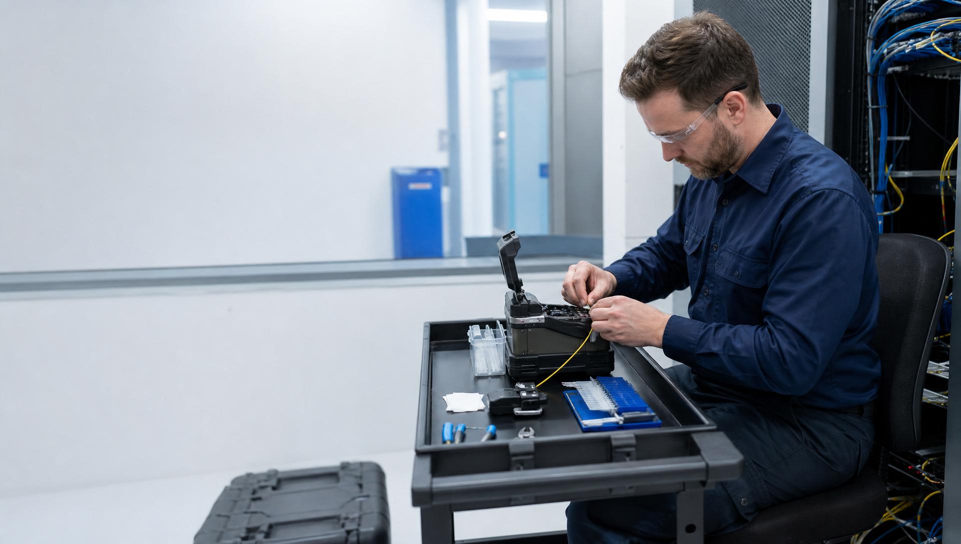
Reliable, high-throughput network infrastructure hinges on the integrity of its optical fiber backbone. When fiber optic cables require extension, repair, or connection to passive components, fusion splicing provides the most optically transparent and mechanically robust solution available. Access Cabling specializes in precision fusion splicing services, delivering connections with consistently sub-0.05 dB average insertion loss. Our C-10/C-7 low-voltage contracting expertise, backed by 28+ years in the field and extensive experience across California and nationwide, ensures optimal signal integrity for mission-critical applications. IT directors, facilities managers, and general contractors seeking superior fiber optic network performance rely on our adherence to TIA/EIA standards, employing only certified technicians and calibrated equipment for every fusion splice.
Precision Fusion Splicing: The Gold Standard for Fiber Optic Connections
Fusion splicing is the process of permanently joining two optical fibers by melting their ends together using an electric arc. This technique produces connections with significantly lower insertion loss and back reflection compared to mechanical splices, crucial for high-bandwidth, long-haul, and single-mode fiber applications. The core principle involves aligning the fiber cores with micron-level precision, then applying a controlled electric discharge to fuse the glass ends into a single, continuous strand. Adherence to industry standards such as TIA/EIA-568-D and BICSI TDMM (Telecommunications Distribution Methods Manual) ensures that all fusion splices meet defined performance criteria for optical loss and mechanical strength. For instance, TIA/EIA-568-D specifies maximum allowable attenuation values for various fiber types, which fusion splicing consistently outperforms, often achieving losses below 0.03 dB per splice for single-mode fiber (SMF) and multimode fiber (MMF).
Design Considerations for Fusion Splicing Implementations
Effective fusion splicing begins with meticulous design and planning, integrating seamlessly into the overall fiber optic network architecture. Engineers must consider cable routing, splice tray capacity, and future expansion requirements. The selection of splice closures, fiber distribution units (FDUs), or optical distribution frames (ODFs) should align with environmental conditions—outdoor pole-mount, direct buried, or indoor rack-mount—and fiber count. For example, a campus backbone requiring 288-strand single-mode fiber will necessitate high-density splice trays that protect individual splices and maintain bend radius compliance (e.g., Corning UCAO closures or Panduit Opticom FDUs). Design must also account for fiber type consistency (OS2 to OS2, OM3 to OM3, etc.), as dissimilar fiber types can introduce excessive loss even with perfect fusion. Furthermore, adequate slack fiber management within closures is paramount to facilitate re-splicing if necessary, without compromising the remaining cable length or exceeding minimum bend radius specifications, typically 10 to 30 times the cable diameter depending on the cable jacket and fiber type as per TIA standards.
Specialized Equipment and Consumables for Optimal Splicing
The quality of a fusion splice is directly correlated with the calibration and sophistication of the equipment used. Access Cabling employs industry-leading fusion splicers from manufacturers like Sumitomo, Fujikura, and Fitel, along with precision cleavers (e.g., Fitel S326/S339 or Fujikura CT50/CT51) and optical time domain reflectometers (OTDRs) such as Fluke Networks OptiFiber Pro or EXFO MaxTester 730C. Consumables are equally critical: fiber optic strippers (e.g., ideal 45-163), isopropyl alcohol (99% pure), lint-free wipes, and splice protection sleeves (e.g., Sumitomo FP-03 series) are standard. Protection sleeves, either heat-shrink or mechanical, encase the fused joint to restore mechanical strength and prevent environmental damage, maintaining the splice's integrity for decades. We only utilize materials compliant with industry specifications, ensuring low attenuation, high return loss, and longevity, whether splicing single-fiber, ribbon fiber, or specialty fiber types. Proper cleaving, producing a fiber end face perpendicular to the fiber axis with minimal angle (typically less than 0.5 degrees), is fundamental prior to fusion, as a poor cleave introduces irreducible loss.
The Fusion Splicing Process: A Step-by-Step Technical Overview
The fusion splicing process is a precise, multi-step operation. First, the fiber jacket is stripped to expose the bare optical fiber, typically to a length of 25-40mm. This is followed by cleaning with 99% isopropyl alcohol and lint-free wipes to remove any contaminants. Next, the bare fiber is precisely cleaved using a high-precision cleaver, ensuring a flat, perpendicular end face. The cleaved fibers are then loaded into the fusion splicer, aligning them in V-grooves. The splicer's internal cameras and optics precisely align the opposing fiber cores in X, Y, and Z axes. An electric arc is then discharged, melting the glass ends and fusing them together. The splicer performs an immediate attenuation estimate, indicating splice loss. Once the splice is complete and its integrity is verified via visual inspection and machine-evaluated loss estimates, a splice protection sleeve is slid over the fused joint and heated in the splicer’s oven, shrinking to reinforce the splice. This entire sequence is performed within controlled environments, minimizing dust and humidity, which are detrimental to splice quality.
Rigorous Testing and Certification for Fusion Spliced Connections
Post-splicing, accurate and thorough testing is non-negotiable to validate the performance of the optical link. Access Cabling adheres to TIA/EIA-568-D.3 for fiber optic cabling and BICSI best practices for testing procedures. Our technicians utilize calibrated test equipment, specifically Optical Time Domain Reflectometers (OTDRs) and Optical Loss Test Sets (OLTS). OTDR testing, performed bidirectionally on each fiber span, identifies splice loss, connector loss, and fiber attenuation over distance, providing a graphical representation of the fiber's characteristics. Single-mode splices are typically expected to show <0.05 dB attenuation, while multimode splices are often <0.1 dB. OTDR results are crucial for troubleshooting and documenting the physical layer. For definitive link loss measurement (Tier 1 Certification), OLTS (Power Meter and Light Source) testing verifies total end-to-end attenuation against calculated budgets, per TIA/EIA specifications. All test results are compiled into comprehensive documentation and certification reports, often in industry-standard formats compatible with Fluke Networks LinkWare Live, guaranteeing transparency and validating performance for our clients.
Key Applications and Use Cases for Fiber Optic Fusion Splicing
Fusion splicing is indispensable across a broad spectrum of commercial and industrial applications where high-performance optical connectivity is paramount. This includes extending existing campus backbone fiber optic infrastructure, deploying fiber-to-the-desk (FTTD) solutions in data-intensive environments like financial trading floors, or establishing fiber links within data centers for inter-rack and intra-building connectivity. It is also critical for repairing accidental fiber optic cable cuts, ensuring minimal downtime and preserving network performance. Furthermore, utility companies rely on fusion splicing for long-haul telecommunications networks and Fiber-to-the-Home (FTTH) deployments. Industrial control systems, medical imaging networks, and security surveillance systems utilizing IP cameras often depend on fusion-spliced fiber for its immunity to EMI/RFI and extended transmission distances. In all these scenarios, the low loss and high mechanical strength offered by fusion splicing provide a robust foundation for reliable data transmission, supporting protocols from 1GbE to 400GbE and beyond.
Ensuring Compliance and Safety in Fiber Optic Splicing Operations
Compliance with industry standards and strict safety protocols is fundamental to all fusion splicing operations performed by Access Cabling. We adhere to the National Electrical Code (NEC) Article 770 for optical fiber cables, ensuring proper installation practices, grounding, and bonding where applicable, and firestopping requirements for cable penetrations. Our technicians are trained in OSHA guidelines for laser safety (Class 1M lasers used in test equipment), proper handling of sharps (bare fiber shards are extremely hazardous), and the use of personal protective equipment (PPE), including safety glasses and gloves. Furthermore, compliance extends to proper disposal of fiber optic waste, which due to its small size and sharp nature, can pose health risks if not managed correctly. All work is performed in accordance with BICSI best practices, manufacturer specifications (e.g., CommScope, Belden), and local permitting requirements specific to California and other jurisdictions, underpinning our commitment to both personnel safety and long-term network reliability.
Access Cabling's Commitment to Superior Fusion Splicing Execution
Access Cabling differentiates itself through a steadfast commitment to engineering excellence, technical proficiency, and unparalleled project execution in fusion splicing. Our C-10/C-7 licensing (CSLB 992009) and 28+ years of experience provide a deep institutional knowledge base that extends beyond basic installation to complex network design, integration, and optimization. We leverage strategic partnerships with leading manufacturers like Panduit, CommScope, Leviton, and Corning, utilizing only top-tier components that are guaranteed for interoperability and performance. Our in-house Project Managers and RCDD-certified staff oversee every phase, from initial site survey and needs assessment to final certification and documentation. What sets us apart is our relentless focus on delivering verifiable, 'right the first time' solutions, minimizing the need for costly remediation. We provide transparent, detailed test reports with every project, ensuring that our clients receive a fiber optic infrastructure that not only meets but often exceeds TIA/EIA performance benchmarks, offering reliability and scalability for years to come.
Advanced OSP Fusion Splicing for Harsh Environmental Durability
Outdoor Plant (OSP) fusion splicing presents unique challenges demanding specialized techniques and materials to ensure long-term reliability in environments ranging from arctic cold to desert heat and high humidity. Unlike indoor plenum-rated installations, OSP fiber optic cables, whether direct-buried, aerial, or contained within conduit, are subject to significant thermal cycling, UV degradation, rodent damage, and hydrostatic pressure. Our methodology for OSP fusion splicing incorporates robust closure selection, such as FOSC (Fiber Optic Splice Closure) or equivalent IP68-rated enclosures, often featuring gel seals or heat-shrinkable tubing providing superior ingress protection. The proper preparation of these closures, including meticulous cable entry sealing and the correct organization of splice trays to maintain bend radius and prevent micro-bending losses, is critical. We utilize splice protectors designed for extreme temperature fluctuations and ensure that all exposed fiber is thoroughly cleaned and sheathed within buffer tubes to prevent moisture wicking. For aerial applications, the mechanical stress on splices from wind load and vibration must be counteracted through appropriate sag calculations and strain relief mechanisms on optical distribution frames (ODFs) or fiber distribution hubs (FDHs). Consideration is also given to the localized electrical environment, such as lightning strike zones, where proper grounding and bonding of metallic cable components and closures are paramount to prevent induced currents from damaging optical components or personnel. Furthermore, for submersible or direct-buried applications, selecting closures with high-impact resistance and resistance to corrosive soil chemicals is a non-negotiable requirement, often necessitating stainless steel components or specialized polymer composites. The planning phase for OSP splicing includes detailed site surveys to assess environmental factors, accessibility for future maintenance, and coordination with civil engineering teams for trenching or pole attachment permits, ensuring the longevity and integrity of the fiber optic infrastructure against the elements. The selection of a fusion splicer with an enhanced environmental operating range and superior arc stability in fluctuating temperatures is also crucial for consistent splice loss performance in these demanding conditions.
Mitigating Common Failure Modes in Fusion Spliced Fiber Optic Links
Despite the inherent strength and low loss of a properly executed fusion splice, several common failure modes can arise if meticulous attention to detail is not maintained throughout the process, leading to degraded performance or complete link failure. One prevalent issue is excessive splice loss, typically exceeding the industry standard of 0.05 dB for single-mode fiber, often attributable to improper fiber cleaving, contaminated fiber ends, or inadequate fusion parameters. A poor cleave angle, characterized by hackle, lip, or planar defects visible under magnification, creates an uneven surface that prevents optimal light transmission. Contaminants like dust, oil, or lint, even microscopic in size, absorb or scatter light, dramatically increasing insertion loss and potentially leading to premature fiber degradation under high power. Improper arc calibration or dirty electrodes in the fusion splicer can result in weak, brittle splices susceptible to environmental stress or handling. Another critical failure mode is insufficient mechanical strength of the splice, making it vulnerable to breaking during handling, coiling within splice trays, or thermal expansion/contraction cycles. This often stems from an improperly centered splice protector sleeve (e.g., inadequate heat shrink, air bubbles within the sleeve, or incorrect sleeve application), which fails to effectively transfer strain away from the fused region. Catastrophic failures can also be triggered by a bend radius violation, either at the splice point itself if the fiber is stressed immediately after fusion and before protector application, or later during installation in tight enclosures, inducing micro- or macro-bending losses. Electrical discharge damage, while rarer, can occur if improper grounding procedures are followed, especially in outside plant installations involving metallic cable components. Furthermore, latent defects, such as microscopic cracks induced during cleaving or fusion, can propagate over time due especially to thermal cycling, causing an intermittent or delayed failure. Comprehensive post-splicing testing, including OTDR (Optical Time Domain Reflectometer) analysis and visual inspection, is indispensable for identifying these potential failure modes before deployment and preventing costly remediation after commissioning. Understanding these fault mechanisms informs our detailed quality control protocols and continuous training for our fusion splicing technicians, emphasizing precision at every step from cleave to enclosure management.
Integration of Fusion Splicing within Data Center Interconnect Topologies
In ultra-low latency, high-bandwidth data center interconnects (DCIs) and structured cabling systems, fusion splicing plays a pivotal role in creating robust, scalable, and manageable fiber optic infrastructures. The typical MPO (Multi-fiber Push On) and MTP (Multifiber Termination Push-on) connectors are efficient for high-density patching and trunking, but for long-haul DCI links between geographically separate data centers or for high-count backbone cabling within a single campus, fusion splicing offers a superior solution in terms of optical performance and TCO. Deploying high-fiber-count trunk cables (e.g., 288-count, 576-count, or even 1728-count and beyond) requires precise mass fusion splicing or ribbon splicing techniques to terminate individual fibers onto pigtails or break-out assemblies. This approach minimizes insertion loss per connection point (often less than 0.03 dB per splice for single-mode in these environments, compared to 0.25-0.75 dB for factory-terminated connectors) and reduces overall signal degradation, which is critical for maximizing reach and minimizing error rates in 400GbE and 800GbE deployments. Within the data center itself, fusion splicing is employed to transition from large backbone cables to smaller distribution frames or panels, connecting diverse equipment like SAN switches, converged network adapters, and high-performance computing (HPC) clusters. This involves meticulous planning for fiber routing within cable management systems, ensuring adequate bend radius for all spliced fibers as they are dressed into splice trays and optical distribution frames (ODFs) or fiber optic patch panels (FOPPs). The long-term scalability of the data center hinges on infrastructure designed for future upgrades, meaning fusion splices must be strategically placed at logical break points to allow for add-drops or reconfigurations without necessitating wholesale cable replacement. Our expertise extends to deploying fusion-spliced pre-terminated fiber optic solutions, where high-count cables are factory-terminated with pigtails or MPO fan-outs, then fusion-spliced on-site to reduce installation time and maintain factory-level performance, a hybrid approach combining the best of both worlds. The precision of fusion splicing also supports wavelength division multiplexing (WDM) and dense wavelength division multiplexing (DWDM) channels, ensuring minimal crosstalk and optimal spectral performance, which are fundamental to maximizing the capacity of data center interconnections.
Strategic Fiber Optic Infrastructure Planning with Fusion Splice Technology Roadmapping
Effective fiber optic infrastructure planning transcends immediate project requirements, embracing a strategic roadmap that anticipates future bandwidth demands, technological advancements, and potential network expansion leveraging fusion splice capabilities. This proactive approach involves not only selecting the appropriate fiber type (e.g., OS2 single-mode for long-reach, OM4/OM5 multi-mode for specific data center applications) but also designing a splice architecture that allows for modular growth and simplified maintenance. We integrate fusion splicing into a comprehensive lifecycle management plan for fiber assets, considering factors such as total cost of ownership (TCO), future proofing, and ease of upgrade. For example, in planning a campus-wide network, rather than point-to-point runs, a spine-and-leaf or distributed topology utilizing organized splice points in intermediate distribution frames (IDFs) or centralized optical distribution frames (ODFs) can enable flexible service delivery and easier fault isolation. This includes allocating dark fiber pairs and pre-splicing buffer slack at strategic access points to facilitate rapid provisioning of new services or connections without extensive re-cabling. The technology roadmap also accounts for emerging fiber optic technologies, such as hollow-core fiber or advanced multi-core fibers, understanding that current splicing techniques and equipment may evolve. We provide detailed documentation deliverables, including CAD drawings, splice schematics, OTDR traces, and fiber assignments, which become invaluable assets for future network management, troubleshooting, and expansion. This documentation ensures that any subsequent splicing or modification work can be performed efficiently and accurately, minimizing downtime. Furthermore, strategic planning includes evaluating the long-term sustainability implications of fiber deployments, balancing initial capital expenditure with operational expense, and considering the environmental impact of materials and energy consumption associated with network components. Our consultative approach ensures that clients not only deploy a state-of-the-art fiber optic network today but also possess a meticulously documented and robust infrastructure capable of adapting to the unforeseen technological demands of tomorrow, with fusion splicing as a cornerstone for unparalleled performance and flexibility over decades of operation.