For organizations requiring robust, high-bandwidth connectivity between telecommunications rooms (TRs) within a building or across a campus, effective backbone cabling is foundational. This critical infrastructure is the arterial network transmitting data, voice, and video signals that support an entire facility's operations. Access Cabling specializes in the design, installation, and certification of enterprise-grade backbone cabling systems, leveraging decades of experience as a licensed C-10/C-7 low-voltage contractor. We understand that backbone infrastructure isn't merely about pulling cable; it's about engineering resilient, scalable, and standards-compliant pathways that minimize latency, maximize throughput, and ensure business continuity. Our approach integrates meticulous planning with advanced fiber optic and copper technologies, adhering strictly to TIA/EIA and BICSI standards to deliver superior performance and reliability, tailored for IT directors, facilities managers, and general contractors seeking uncompromising quality in their network foundations.
Defining Backbone Cabling and Its Critical Role
Backbone cabling, also known as riser cabling or vertical cabling, is the inter-building and intra-building cable infrastructure connecting telecommunications rooms, equipment rooms, and entrance facilities. Unlike horizontal cabling that serves individual workstations, backbone cabling supports aggregated traffic, making its performance paramount to overall network efficiency. This system typically includes the backbone cables themselves, intermediate and main cross-connects, mechanical terminations, and patch cords or jumpers used for backbone-to-backbone or backbone-to-horizontal cross-connection. The choice of media—whether single-mode fiber (OS1/OS2), multi-mode fiber (OM3/OM4/OM5), or twisted-pair copper (Category 6A, 7, 8)—is determined by distance, bandwidth requirements, future scalability, and budget. Our designs strictly follow TIA-568.0-D and TIA-568.1-D guidelines, which define backbone cabling hierarchy, distances, and media types, ensuring the system meets current and anticipated network demands, including demanding applications like 100 Gigabit Ethernet and Fibre Channel.
Strategic Planning and System Design Considerations
Effective backbone design begins with a comprehensive assessment of current and future network requirements. This involves analyzing building blueprints, identifying TR locations, understanding anticipated data growth, and considering environmental factors. Key design considerations include defining the cabling topology (e.g., star, hierarchical star), determining optimal cable routing pathways (riser shafts, conduits, aerial, underground), and selecting appropriate cable types based on transmission distances and bandwidth targets. For fiber optic backbones, specifying the core size (e.g., 50/125 for multimode, 9/125 for singlemode), jacket ratings (e.g., OFNP for plenum, OFNR for riser), and connector types (LC, SC, MPO) is crucial. Our engineers utilize BICSI TDMM methodologies, employing tools like optical time-domain reflectometers (OTDRs) during the design phase to anticipate performance characteristics and ensure future compatibility with evolving hardware, adhering to TIA-569-D for telecommunications pathways and spaces, which directly impacts the backbone's longevity and performance.
Advanced Fiber Optic Media and Connector Selection
Fiber optic cabling is the predominant choice for high-speed backbone applications due to its superior bandwidth, immunity to electromagnetic interference (EMI), and extended transmission distances. Access Cabling specifies and deploys various fiber types from manufacturers like Corning, Belden, and CommScope. For intra-building links up to 550 meters supporting 10 Gigabit Ethernet, OM3 and OM4 multimode fiber are common; OM5 extends this with support for wavelength division multiplexing (WDM) technologies. For inter-building or longer intra-building distances, and for future-proofing beyond 100GbE, single-mode fiber (OS2) is the standard, allowing transmission over tens of kilometers. Connector selection is equally critical; LC connectors are prevalent for fiber-to-the-desk and patching, while MPO/MTP connectors are increasingly used for high-density fiber trunking, particularly in data center backbones, facilitating rapid deployment and scalability. Proper cable construction, such as loose-tube or tight-buffered designs, is chosen based on environmental conditions and connectorization methods, ensuring mechanical protection and optimal optical performance.
Precision Installation and Pathway Management
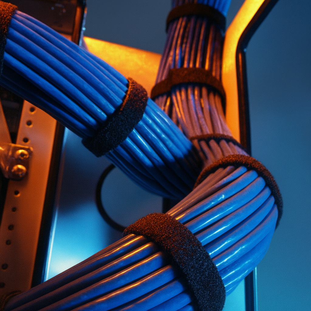
The physical installation of backbone cabling requires meticulous attention to detail to preserve transmission characteristics and ensure compliance with building codes and standards such as NEC (NFPA 70). Our certified technicians are proficient in deploying fiber optic cables through various pathways, including vertical riser shafts, suspended ceilings, underground conduits, and aerial routes. Critical aspects include proper cable tension during pulls to prevent microbends and macrobends that degrade optical performance, adherence to minimum bend radii as specified by cable manufacturers (e.g., Panduit, Leviton), and secure cable management within trays, ladders, and conduits. For inter-building installations, considerations for direct burial, duct bank systems, and lightning protection are integrated into the deployment strategy. All installation practices conform to BICSI ITSIMM standards, minimizing signal loss and ensuring the physical integrity of the entire backbone infrastructure, from headend to termination point.
Comprehensive Testing and Certification Protocols
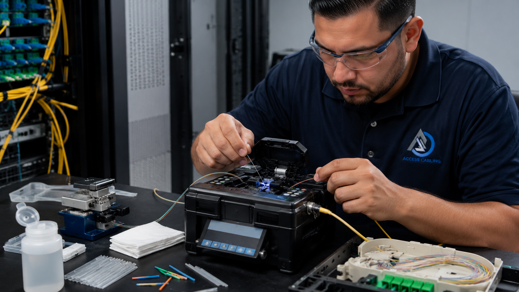
Post-installation, rigorous testing and certification are non-negotiable for backbone cabling to validate performance and guarantee compliance. For fiber optic backbones, we utilize advanced Fluke Networks DSX-series certifiers to perform Tier 1 (Loss/Length) and Tier 2 (OTDR) testing. Tier 1 testing measures insertion loss and length using an Optical Loss Test Set (OLTS) and power meter in accordance with TIA-568.3-D. Tier 2 testing employs an OTDR to characterize the entire fiber link, identifying splices, connectors, and any anomalies, providing a graphical representation of the fiber's attenuation profile. Each fiber strand is tested bi-directionally at multiple wavelengths (e.g., 850/1300nm for multimode, 1310/1550nm for single-mode) to ensure compliance with specified attenuation budgets and TIA/EIA performance limits. All test results are documented and provided in comprehensive reports, offering irrefutable proof of system performance and facilitating future troubleshooting and warranty claims.
Ensuring Regulatory Compliance and Safety Standards
Adherence to industry regulations and safety standards is paramount in all backbone cabling projects. Access Cabling operates under CSLB license 992009, specifically licensed for C-10 Electrical and C-7 Low Voltage Systems, ensuring all work complies with the California Building Code, including structural, mechanical, electrical, and plumbing provisions. We strictly follow the National Electrical Code (NEC) articles related to communications circuits (e.g., Article 800 for Communications Circuits and Article 770 for Optical Fiber Cables), which dictate cable types, fire ratings (e.g., riser-rated OFNR, plenum-rated OFNP), grounding, and bonding requirements. Further, our safety protocols align with OSHA standards regarding work at height, confined spaces, and electrical safety. This comprehensive approach to compliance not only mitigates risks but also ensures that the installed backbone infrastructure is safe, legally compliant, and robust for its operational lifespan.
Access Cabling's Differentiated Backbone Expertise
What sets Access Cabling apart in backbone infrastructure deployment is our unwavering commitment to engineering excellence and client-specific solutions, backed by 28+ years of nationwide experience. We reject one-size-fits-all approaches, instead focusing on a deep understanding of each client's unique operational demands and growth trajectory. Our team consists of BICSI-certified RCDDs (Registered Communications Distribution Designers) and certified installers well-versed in the latest TIA/EIA standards and manufacturer best practices from industry leaders like Panduit, CommScope, and Leviton. We provide full project lifecycle support, from initial needs assessment and meticulous design to expert installation, rigorous testing with Fluke DSX-8000 certifiers, and comprehensive documentation packages. Our proactive communication and transparent project management ensure that complex backbone deployments are executed efficiently, on time, and within budget, delivering a future-ready network foundation that exceeds expectations and provides unparalleled reliability for critical business operations.
Interfacing Backbone Systems with Building Infrastructure and MEP
The successful implementation of a robust backbone cabling system extends beyond merely pulling fiber; it critically involves meticulous coordination and integration with the overarching building infrastructure and mechanical, electrical, and plumbing (MEP) trades. Early engagement during the design phase is paramount to avoid costly conflicts and reworks. For instance, determining optimal conduit sizing and pathways for OM4/OS2 fiber optic cables often clashes with HVAC ducting, plumbing lines, or high-voltage electrical runs. We leverage Building Information Modeling (BIM) tools like Autodesk Revit to perform clash detection, ensuring that dedicated cable trays, conduits (e.g., rigid metallic conduit for fire-rated areas, intermediate metallic conduit in equipment rooms), and plenum-rated cable pathways are properly allocated and sized (e.g., 4-inch rigid steel conduit for major riser pathways extending between telecommunications rooms) without impeding other critical building systems. Consideration must be given to seismic bracing requirements (e.g., per TIA-222-G/H) for overhead cable trays and racks in data centers, which necessitates structural load calculations and coordination with structural engineers. Moreover, firestopping applications for penetrations through fire-rated walls and floors (e.g., using UL-listed firestop collars or sealants with appropriate F and T ratings) are non-negotiable for adhering to building codes (e.g., NFPA 70, local fire marshal requirements) and ensuring life safety, requiring close collaboration with fire protection specialists and general contractors. Proper grounding and bonding of metallic pathways and enclosures, consistent with IEEE 1100 and TIA-607-C standards, also requires careful planning with the electrical contractor to prevent ground loops and ensure equipment protection.
Ensuring Data Security and Resilience in Backbone Network Design
The backbone network, as the superhighway of an organization's data, represents a prime target for both physical and cyber threats, necessitating a design philosophy deeply rooted in security and resilience. Physical security measures for main distribution frames (MDFs) and intermediate distribution frames (IDFs) are critical, including access control systems (e.g., biometric readers, proximity cards), surveillance (CCTV), and robust physical enclosures (e.g., locked cabinets, secure cages) to prevent unauthorized access to crucial fiber patch panels and active equipment. We implement diverse routing strategies, where feasible, utilizing multiple geographically separated pathways for redundant fiber runs between critical data centers or telecommunications rooms. This mitigates the risk of a single point of failure from accidental cuts or deliberate attacks. Furthermore, within the fiber infrastructure itself, considerations such as installing armored fiber optic cables (e.g., steel tape armored, interlocking armored) in high-risk outdoor or industrial environments protect against rodent damage, crushing, and unauthorized tapping. For sensitive applications, dark fiber offers enhanced security by providing a dedicated, unshared physical medium, reducing exposure to network compromises. Network segregation through VLANs and physical separation of critical data pathways (e.g., SCADA networks vs. corporate networks) reinforces security at the architectural level. Redundant power supplies for active equipment and UPS systems with adequate runtime (e.g., 30-minute runtime) ensure operational continuity during power outages, complementing the physical layer resilience. These measures, integrated from the earliest design stages, forge a backbone resistant to both environmental and malicious disruptions.
Strategic Technology Roadmapping and Future-Proofing Backbone Cabling
Future-proofing a backbone cabling infrastructure involves a strategic technology roadmap that anticipates evolving bandwidth demands, emerging standards, and potential technological shifts over a typical 15-20 year lifecycle. Adopting a modular, scalable architecture is fundamental. For instance, deploying a higher-count fiber optic cable (e.g., 144-strand OS2 single-mode fiber rather than 48-strand) even if not immediately fully utilized, significantly reduces future installation costs and disruption when bandwidth needs inevitably increase. Similarly, choosing MPO/MTP connectivity for high-density environments now enables seamless migration to 40G Ethernet (e.g., using 8-fiber MPO for 40GBASE-SR4) and 100G Ethernet (e.g., 24-fiber MPO for 100GBASE-SR10) and beyond without recabling. Current trends indicate a strong move towards single-mode fiber (OS2) for campus backbones and data center uplinks due to its virtually unlimited bandwidth potential and reach, offering superior return on investment compared to multi-mode fiber for long-term scalability. We also consider the physical space constraints and growth potential within existing telecommunications rooms and data centers, designing for increased cabinet density and efficient cable management systems (e.g., high-density trunking, vertical cable managers). Evaluating emerging technologies like SWDM (Short Wavelength Division Multiplexing) for extending multi-mode fiber capabilities or future developments in silicon photonics impacts fiber type selection. Regular capacity planning exercises, coupled with a deep understanding of IEEE Ethernet standards roadmaps (e.g., 400GbE, 800GbE), allow us to recommend appropriate cable types, connector interfaces, and patching solutions that will support next-generation network equipment without requiring a complete overhaul of the physical layer infrastructure.
Detailed Documentation, Asset Management, and Lifecycle Maintenance
Comprehensive documentation is not merely an administrative task; it is the cornerstone of efficient backbone network management, troubleshooting, and future expansion. From the initial design phase through final commissioning, we provide a complete set of deliverables including as-built drawings (e.g., AutoCAD, Visio diagrams detailing exact cable routes, splice locations, and termination points), fiber trunk schematics, and port-to-port connectivity maps for all active and passive components within the backbone. This includes precise labeling conventions adhering to TIA-606-C standards for every cable, patch panel port, and splice tray, ensuring unambiguous identification. Beyond physical documentation, detailed asset management involves creating a robust database (e.g., utilizing DCIM software or specialized cabling management platforms) that tracks each fiber strand's characteristic (e.g., length, type, test results), its current assignment, and available spare capacity. This allows for rapid fault isolation, efficient capacity planning, and informed decision-making during upgrades or modifications. Furthermore, a defined lifecycle maintenance program is crucial. This encompasses scheduled visual inspections of cable pathways, environmental checks in MDFs/IDFs (temperature, humidity), and periodic re-testing of critical fiber links (e.g., using OTDR and optical loss test sets per TIA-568.3-D) to detect gradual degradation or potential vulnerabilities before they lead to outages. Our documentation package also includes warranty information, manufacturer specifications for all installed components, and recommended maintenance schedules, empowering clients with a complete operational blueprint for their backbone infrastructure for its entire service life.