Ensuring the reliability and performance of modern network infrastructure necessitates rigorous, verifiable testing. Access Cabling specializes in comprehensive cable and fiber testing, leveraging Fluke Networks' Versiv platform, including the DSX CableAnalyzer series and CertiFiber Pro, to provide irrefutable proof of compliance and operational readiness. This critical service is designed for IT directors, facilities managers, and general contractors who demand certainty in their physical layer investment, whether commissioning new builds, upgrading existing networks, or diagnosing intermittent issues. Unlike general-purpose electrical contractors, Access Cabling's 28+ years of C-10/C-7 low-voltage expertise, combined with advanced Fluke testing methodologies, delivers precise, standards-compliant certification data, ensuring your network performs optimally from day one and throughout its lifecycle.
The Imperative of Fluke Certification for Network Performance
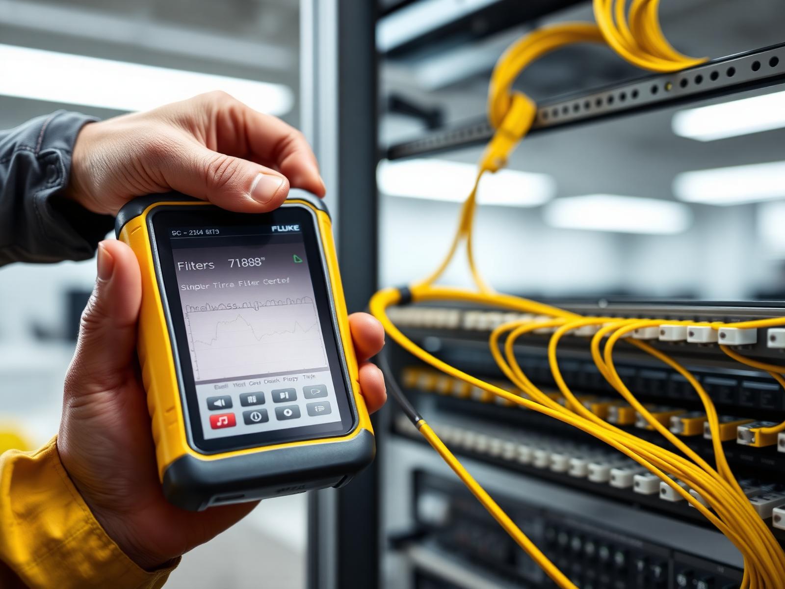
Fluke certification testing is not merely a diagnostic step; it is a fundamental requirement for validating the performance and adherence to industry standards for structured cabling systems. Utilizing platforms like the Fluke DSX-8000 CableAnalyzer for copper and the CertiFiber Pro for fiber optic infrastructure, Access Cabling performs Level 2G / Level IIIe testing as defined by ANSI/TIA-1152-A. This rigorous process measures key parameters such as Near-End Crosstalk (NEXT), Return Loss (RL), Insertion Loss (IL), Propagation Delay, and Delay Skew for copper, ensuring that each link meets or exceeds the specifications for its category (e.g., Cat6A, Cat8). For fiber, we test for loss/attenuation, length, and polarity, utilizing methods like Tier 1 loss/length testing per TIA-568.3-E and IEC 61280-4-1 (for multimode) or IEC 61280-4-2 (for singlemode). These measurements are critical because even a seemingly minor deviation in any of these parameters can cause packet loss, reduced bandwidth, and intermittent connectivity issues that are notoriously difficult to troubleshoot at higher network layers. Our adherence to these standards, coupled with the calibrated accuracy of Fluke equipment, provides a verifiable audit trail for every tested link.
Interpreting Test Results and Understanding Pass/Fail Criteria
Understanding the pass/fail criteria for Fluke test results is paramount to proper network validation. For copper cabling, the DSX platform automatically compares measured values against the selected TIA or ISO/IEC standard limit line for the specified cabling type (e.g., TIA Cat 6A Permanent Link or Channel). A 'Pass' indicates that all measured parameters fall within the acceptable thresholds. A 'Fail' requires immediate investigation, often indicating issues like incorrect terminations, damaged cables, excessive untwisting, or improper patch cord usage. Our technicians are trained not just to run tests, but to interpret detailed graphs and S-parameters, pinpointing the specific fault location and nature. For fiber, Tier 1 testing checks for optical loss budget compliance, ensuring the end-to-end attenuation including connectors and splices does not exceed the calculated budget for the application. Fluke's LinkWare software consolidates these results into comprehensive reports, providing granular detail on each parameter, including graphical representations of frequency-dependent measurements, which are invaluable for diagnosing subtle performance degradations that might otherwise go unnoticed. This detailed analysis prevents future costly downtime and ensures long-term network stability.
Advanced Fiber Optic Testing with CertiFiber Pro and OTDR
Beyond basic Tier 1 loss testing for fiber, Access Cabling employs the Fluke CertiFiber Pro for advanced optical loss measurements and the OptiFiber Pro OTDR (Optical Time Domain Reflectometer) for comprehensive Tier 2 certification. While Tier 1 validates total insertion loss against a calculated budget using a light source and power meter, Tier 2 adds the critical capability of characterizing individual events (splices, connectors, and bends) along the fiber link. The OptiFiber Pro's OTDR function injects light pulses into the fiber and measures the reflected and backscattered light, generating a trace that visually maps the fiber's physical characteristics. This allows for precise identification of fault locations, attenuation of individual components, and detection of macrobends or microbends that could degrade performance. Crucially, OTDR testing verifies the quality of splices and connectors, providing attenuation per event, distance to events, and overall link loss. This level of detail is indispensable for mission-critical fiber backbone links, data center interconnects, and campus networks, ensuring not just functionality, but optimal performance and easy fault location for future maintenance. We perform both singlemode and multimode OTDR testing, adhering to TIA-568.3-E and ISO/IEC 11801 standards.
Ensuring Accuracy: Test Reference Cords and Calibration
The integrity of any certification test hinges on the accuracy of the testing equipment and the methodology employed. Access Cabling strictly adheres to manufacturer guidelines concerning Test Reference Cords (TRCs) and tester calibration. For copper permanent link testing, we utilize Fluke-approved Permanent Link Adapters and Channel Adapters with verified, high-quality reference cords that are routinely inspected for damage and wear. Dirty or damaged TRCs are a leading cause of 'false fails' or, worse, 'false passes,' which can lead to significant troubleshooting headaches down the line. Our technicians are trained to perform daily TRC verification checks before testing commences, and any TRC showing signs of degradation is immediately replaced. Similarly, for fiber optic testing with the CertiFiber Pro, perfectly clean and high-quality launch and tail cords are essential. These TRCs must meet specific reference-grade requirements (e.g., IEC 61753-1 Category 1) to ensure accurate loss measurements. Furthermore, all our Fluke Versiv units undergo annual factory calibration by Fluke Networks, ensuring that the measurement accuracy remains within published specifications. This meticulous attention to TRCs and calibration is a non-negotiable aspect of our quality assurance, guaranteeing reliable and repeatable test results.
Post-Installation Fluke Certification and Documentation
Upon completion of all cabling installation and testing, Access Cabling provides comprehensive certification documentation generated directly from Fluke Networks' LinkWare Live or LinkWare PC software. This documentation is not just a summary; it's a detailed, per-link report containing all measured parameters against the specified pass/fail limits. Each report includes graphical traces for NEXT, return loss, and other critical measurements, along with the device under test's unique identifier, test limits applied, and date/time stamps. For fiber, OTDR traces with event tables are included for Tier 2 certification. This robust documentation package serves multiple crucial purposes: it provides irrefutable proof that the installed cabling meets or exceeds industry standards (e.g., TIA-568.0-E, TIA-568.1-E, ISO/IEC 11801); it is often a mandatory requirement for manufacturer warranties (e.g., CommScope, Panduit, Belden 25-year warranties); and it acts as an invaluable baseline for future network upgrades, troubleshooting, or expansion. Our thorough documentation package ensures that facilities managers and IT directors have a complete, verifiable record of their network's physical layer performance, simplifying future maintenance and protecting their infrastructure investment.
Mitigating Future Issues Through Proactive Fluke Diagnostics
Beyond post-installation certification, Fluke testing is an invaluable tool for proactive network maintenance and troubleshooting. Intermittent network issues, often attributed to higher-layer protocols, frequently have their root cause in the physical layer. Utilizing the Fluke DSX CableAnalyzer's advanced diagnostics, Access Cabling can quickly isolate faults such as split pairs, poor termination quality, or impedance mismatches that might not cause a hard 'fail' but contribute to degraded performance. For example, excessive Insertion Loss or Return Loss can lead to retransmissions at the data link layer, effectively reducing throughput. Our technicians can perform diagnostic tests on existing infrastructure, providing a 'health check' that identifies potential bottlenecks or weak points before they lead to critical failures. This proactive approach is particularly beneficial for aging infrastructure, data center migrations, or when integrating new, higher-bandwidth equipment into an existing network. By identifying and rectifying these subtle physical layer anomalies, we help prevent costly downtime, improve operational efficiency, and extend the lifespan of existing cabling systems, ensuring network stability and reliability.
Access Cabling's Unwavering Commitment to Testing Excellence
Access Cabling's differentiator in the realm of Fluke testing stems from our unwavering commitment to technical excellence and deep understanding of network physics, not just equipment operation. Our CSLB C-10/C-7 licensing and 28+ years of dedicated low-voltage experience mean we bring an unparalleled level of expertise to every project. We don't just own Fluke testers; our certified technicians possess profound knowledge of TIA/EIA, BICSI, and NEC standards, understanding the 'why' behind each test parameter and its impact on network performance. This allows us to accurately configure test limits, interpret complex waveforms, and provide actionable recommendations for resolving issues. We use only up-to-date, factory-calibrated Fluke Versiv platforms, ensuring legally defensible and scientifically accurate results. Our methodical approach, from pre-test planning and thorough record-keeping to insightful post-test analysis and comprehensive documentation, solidifies our position as a trusted partner. Choosing Access Cabling means partnering with a firm that prioritizes the long-term reliability and performance of your critical network infrastructure, delivering confidence through verifiable, industry-standard Fluke certification.
The Critical Role of Test Limits in Certification
Accurate Fluke certification hinges entirely upon the correct selection and application of test limits, which dictate the pass/fail criteria for a given cable run. For copper cabling, this typically involves adherence to TIA-568.C or ISO/IEC 11801 standards, specifying parameters like insertion loss, return loss, near-end crosstalk (NEXT), power sum NEXT (PSNEXT), equal-level far-end crosstalk (ELFEXT), power sum ELFEXT (PSELFEXT), delay skew, and propagation delay. Each cabling category (e.g., Cat 5e, Cat 6, Cat 6A, Cat 8) has progressively stricter limits defined by these standards, directly correlating to higher bandwidth and reduced error rates. For instance, a Cat 6A installation supporting 10GBASE-T must meet far more stringent alien crosstalk (AXT) limits than a Cat 5e system, requiring meticulous installation practices and often, shielded cabling solutions. In optical fiber testing, the chosen test limits depend on the fiber type (multimode OM1-OM5, singlemode OS1/OS2) and the application (e.g., 10GBASE-SR, 100GBASE-LR4), with limits typically derived from IEEE 802.3 standards for Ethernet or TIA/EIA-568 series for premises cabling. Loss budgets are calculated based on cable length, connector count, and splice count, applying industry-standard attenuation values (e.g., 0.5 dB per connector, 0.3 dB per splice, 0.5-3.5 dB/km for multimode, 0.4-0.5 dB/km for singlemode at 1310/1550 nm). Misconfiguring test limits, such as selecting a Cat 5e limit for a Cat 6A installation, will incorrectly report a 'Pass' due to the looser thresholds, leading to intermittent network performance issues that are often difficult and costly to diagnose post-installation. Our engineers meticulously cross-reference project specifications, equipment datasheets, and current industry standards to guarantee the appropriate test limits are applied for every single link, preventing costly retesting and ensuring the network meets its full performance potential from day one.
Streamlining Project Workflow with Fluke LinkWare Live Integration
Efficient project management and data integrity in large-scale cabling deployments are significantly enhanced through the utilization of Fluke Networks' LinkWare Live cloud service. This platform serves as a central repository for all test results generated by Versiv series testers (e.g., DSX-8000, CertiFiber Pro, OptiFiber Pro), allowing for real-time collaboration and project oversight across multiple teams and geographic locations. Prior to on-site testing, project managers can pre-configure test setups, cable IDs, and test limits within LinkWare Live and push these configurations directly to the testers. This eliminates potential human errors during manual setup on the field and ensures consistency across all technicians. As testing progresses, results are uploaded automatically or manually from the testers to the cloud, providing instantaneous visibility into project status, pass/fail rates, and potential issues. This real-time reporting capability is critical for identifying common failure modes early on, such as continuity errors on specific racks or excessive return loss on a particular cable type, enabling immediate corrective action rather than discovering these issues at project completion. Furthermore, LinkWare Live simplifies the creation of comprehensive certification reports, which can be customized with client logos, project details, and specific data points, generating professional, auditable documentation in PDF or XML formats. This digital workflow not only reduces administrative overhead but also provides an immutable record of network performance, indispensable for warranty claims, regulatory compliance, and future network upgrades. The integration of site surveys, design parameters, and test results within a singular, accessible platform significantly de-risks complex cabling projects by ensuring transparent, verifiable compliance at every stage.
Mitigating RF Interference: Crosstalk and Alien Crosstalk Diagnostics
In local area networks, particularly those deploying Cat 6A and higher, electromagnetic interference (EMI) severely degrades performance. Crosstalk, specifically Near-End Crosstalk (NEXT) and Far-End Crosstalk (FEXT), occurs when an electrical signal in one wire pair induces a signal in an adjacent pair within the same cable sheath. Fluke testers like the DSX-8000 measure these parameters by injecting a signal into one pair (the disturbing pair) and quantifying the induced noise on other pairs (the disturbed pairs). High NEXT values often indicate poor termination practices, excessive untwisting of pairs at connectors, or manufacturing defects in the cable itself. FEXT, and its derived parameter ELFEXT (Equal-Level Far-End Crosstalk), are critical for evaluating signal quality at the receiving end. Beyond internal cable crosstalk, Alien Crosstalk (AXT) presents a significant challenge in high-density environments. AXT refers to the unwanted signal coupling between adjacent cables or between cables in adjacent bundles. For 10GBASE-T deployments over Cat 6A, AXT is often the limiting factor, as the higher frequencies used make cables more susceptible to external noise sources. Fluke testers equipped with AXT measurement capabilities employ specific test adapters and methodologies to measure coupling between neighboring cables, which is a complex test requiring multiple cable runs to be simultaneously characterized. Mitigation strategies for AXT include maintaining proper cable separation, using shielded cabling (F/UTP, S/FTP) and shielded connectors, and ensuring correct grounding and bonding of these shielded systems. The detailed diagnostic graphs provided by Fluke testers, such as frequency-domain plots of NEXT, FEXT, and AXT, allow our technicians to pinpoint the exact frequency ranges and locations where interference is greatest, facilitating precise troubleshooting and remediation, which might involve repositioning cables, re-terminating links, or implementing specialized cable management techniques to maintain channel performance.
Advanced Power over Ethernet (PoE) Testing and Validation
The widespread adoption of Power over Ethernet (PoE) for powering IP devices, such as WAPs, IP cameras, and VoIP phones, introduces new complexities in cable certification. Fluke Networks' Versiv platform, particularly with the DSX-8000, offers advanced capabilities to validate cabling infrastructure for PoE operation, ensuring sufficient power delivery without compromising data integrity. Traditional cable tests (continuity, wire map, length) are insufficient to guarantee robust PoE performance. The DSX series can perform a Resistance Unbalance test, which is critical for PoE. Unequal resistance in the conductor pairs (measured in ohms) can cause current to flow unevenly, leading to premature cable aging, increased heat, degraded data signal performance, or even equipment malfunction. Type 2 (PoE+) and Type 3/4 (PoE++/4PPoE, up to 100W) standards specify very tight resistance unbalance limits both within a pair and between pairs. Our technicians rigorously test for these parameters, identifying potential issues caused by poor quality cable, improper termination, or damaged conductors. The DSX also provides an actual power test, allowing the operator to connect a load and simulate power draw to verify that the power sourcing equipment (PSE) can deliver the required wattage across the cable length to the powered device (PD). This end-to-end PoE validation ensures that the installed cabling can reliably support the power demands of connected devices, preventing costly outages or premature equipment failure that would occur if only basic continuity tests were performed. This proactive verification is crucial for mission-critical PoE applications in smart building systems or security deployments, where continuous power delivery is paramount.