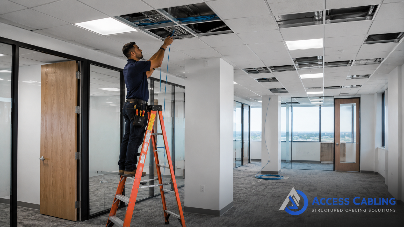
Establishing robust and reliable telecommunications infrastructure is foundational for any modern enterprise. Access Cabling specializes in the meticulous planning, installation, and certification of Telecommunications Cabling systems, specifically addressing the critical pathways from the Main Point of Entry (MPOE) and Demarcation Point (Demarc) to the Main Distribution Frame (MDF) or intermediate distribution frames. Our services are engineered for IT directors, facilities managers, and general contractors who demand uncompromising performance, adherence to TIA/EIA and BICSI standards, and a future-proof foundation for their voice, data, and multimedia communications. Unlike generalized cabling providers, Access Cabling brings 28 years of specialized expertise as a licensed C-10/C-7 low-voltage contractor (CSLB 992009), ensuring every MPOE build-out, demarc extension, or MDF integration is executed with precision, compliance, and an intrinsic understanding of carrier requirements and property owner responsibilities. We eliminate the guesswork and mitigate common pitfalls associated with carrier hand-offs and internal network integration.
Defining Telecommunications Cabling and Its Critical Role
Telecommunications Cabling, in this context, refers to the essential infrastructure that bridges the external telecommunications network, often provided by an Incumbent Local Exchange Carrier (ILEC) or Competitive Local Exchange Carrier (CLEC), with an organization's internal network. This critical pathway commences at the MPOE, where external carrier lines enter the building, and extends to the Demarcation Point, which marks the precise hand-off of responsibility from the carrier to the customer. Access Cabling designs and installs the subsequent extensions from this Demarc to the MDF, the central point for telecommunications equipment within the facility. Adherence to TIA-569-D (Telecommunications Pathways and Spaces) and TIA/EIA-568 series for horizontal and backbone cabling ensures proper pathway sizing, cable support, and signal integrity from the carrier interface inward. This foundational cabling is imperative for services ranging from traditional POTS lines and T1/E1 circuits to modern fiber optic broadband connections, providing the necessary pathways for voice communication, internet access, and dedicated data lines that form the lifeblood of business operations.
Strategic Design and Engineering for Carrier Hand-offs
Effective telecommunications cabling design necessitates a comprehensive understanding of both carrier specifications and internal network architecture. Access Cabling’s engineering process begins with a detailed site survey and a thorough review of LEC/CLEC circuit designs, including entrance facility requirements from providers like AT&T, Verizon, or Spectrum. We specify appropriate entrance conduits, often Schedule 40 or 80 PVC, correctly sized for future expansion per TIA-569-D guidelines. Our designs account for proper grounding and bonding, essential for surge protection and compliance with NEC Article 800, using specific grounding electrodes and bonding conductors. The choice of cable type for demarc extensions – whether multi-pair copper (e.g., Cat3, Cat5e for voice, or higher counts like 25-pair, 50-pair, 100-pair for trunks), single-mode fiber optic cable (OS2), or multi-mode fiber (OM3/OM4) for high-bandwidth data applications – is dictated by the carrier service and the customer’s internal network requirements. Our blueprints include precise layouts for cross-connect fields, patch panel designations, and termination blocks at the MDF, such as 110 blocks or 66 blocks for voice, and fiber distribution panels or copper patch panels for data, ensuring seamless integration and manageability.
Optimal Materials and Components for Demarc Integration
The longevity and performance of telecommunications cabling hinge on the selection of high-quality, standards-compliant materials. For copper-based demarc extensions, Access Cabling utilizes plenum-rated (CMP) or riser-rated (CMR) multi-pair copper cables from manufacturers like Belden or CommScope, ensuring fire safety and performance over specified distances. We deploy industry-standard 110 blocks or Krone-style connecting blocks for voice circuits at the MDF, ensuring reliable IDC (Insulation Displacement Connection) terminations. For fiber optic extensions from the demarc, we specify durable indoor/outdoor tight-buffered or loose-tube fiber optic cables from Corning or Panduit, terminated with LC, SC, or ST connectors, as dictated by the active equipment. Fiber optic patch panels, such as those from Leviton or Corning, are used within the MDF to provide organized interconnection points. Entrance protection devices, such as lightning arrestors and surge suppressors, are carefully integrated at the MPOE to safeguard internal equipment, adhering to grounding and bonding requirements outlined in BICSI TDMM and NEC. Every component, from cable trays to grounding busbars, is selected for its robust performance characteristics and compliance with industry best practices.
Meticulous Installation Protocols for Seamless Operation
Access Cabling’s installation methodology for telecommunications cabling is characterized by meticulous attention to detail and strict adherence to TIA/EIA and BICSI installation standards. Our C-10/C-7 licensed technicians are proficient in routing cables through appropriate pathways, ensuring proper bend radius is maintained for both copper and fiber to prevent signal degradation or premature cable failure. For multi-pair copper, termination onto 110 blocks or 66 blocks follows specific color codes (e.g., T568A/B for data, 25-pair color code for voice) and ensures gas-tight connections. Fiber optic cable fusion splicing or mechanical termination is performed using precision tools, maintaining low insertion loss and reflection. We implement robust cable management systems within the MDF, including vertical and horizontal cable managers, to facilitate future MAC (Moves, Adds, Changes) work and maintain an organized environment. All installation practices prioritize firestopping for penetrations, proper labeling of all cables and termination points, and clear identification of the demarcation point, critical for operational efficiency and compliance audits.
Comprehensive Testing and Certification for Carrier Connectivity
Post-installation, robust testing and certification are paramount to guarantee the integrity and performance of the telecommunications cabling infrastructure. For copper-based extensions, Access Cabling utilizes Fluke Networks DSX series cable analyzers to perform comprehensive tests including wiremap, length, propagation delay, delay skew, NEXT (Near-End Crosstalk), FEXT (Far-End Crosstalk), and return loss, ensuring compliance with ISO/IEC and TIA performance parameters for voice-grade and data-grade copper cabling. Each pair on multi-pair voice cables is continuity tested for shorts, opens, and crossed pairs. For fiber optic demarc extensions, we employ Optical Loss Test Sets (OLTS) like Fluke Networks SimpliFiber Pro or OTDRs (Optical Time Domain Reflectometers) to measure insertion loss, optical return loss (ORL), and identify any anomalies such as macrobends or poor splices. All test results are documented in a comprehensive certification report, providing a detailed record of performance and serving as an essential validation for the client, confirming that the installed system meets or exceeds industry standards and manufacturer specifications, and is ready for carrier turn-up.
Typical Use Cases and Applications of Robust Telecom Cabling
The applications for high-quality telecommunications cabling are diverse and critical across commercial, industrial, and institutional sectors. Common use cases include: establishing primary and redundant carrier feeds for data centers, enabling multi-line voice services for call centers or large office complexes, extending dedicated internet access (DIA) circuits from the building entrance to an internal data room or server closet, facilitating PRI (Primary Rate Interface) or SIP trunking services for VoIP systems, and supporting building automation systems (BAS) that rely on external connectivity. For multi-tenant units (MTUs) or multi-dwelling units (MDUs), robust telecommunications cabling is essential for distributing carrier services to individual tenant spaces. In larger campuses or facilities, this cabling infrastructure also feeds campus-wide backbone networks originating from a central MPOE. Each application underscores the necessity of a reliable, standards-compliant demarc extension to ensure uninterrupted business operations and seamless connectivity to the global network.
Crucial Compliance and Safety Measures for Building Entrances
Compliance and safety are non-negotiable elements in telecommunications cabling, particularly at the building entrance facility. Access Cabling strictly adheres to all applicable codes and standards, including the National Electrical Code (NEC) Article 800 (Communications Circuits) and Article 250 (Grounding and Bonding). Proper grounding and bonding of metallic components, surge protection devices, and cable shields are meticulously implemented to prevent electrical hazards and mitigate electromagnetic interference (EMI). Firestopping of all cable penetrations through fire-rated walls and floors is performed using UL-listed materials to maintain compartmentalization and comply with fire safety regulations. Our installations incorporate appropriate labeling per TIA-606-C standards, providing clear identification of cables, pathways, and termination points, which is vital for maintenance, troubleshooting, and emergency response. All work is performed by licensed professionals who understand the specific requirements for working within MPOE rooms, telecom closets, and electrical equipment spaces, ensuring both personnel safety and system integrity throughout the project lifecycle.
Access Cabling’s Differentiated Approach to Carrier Infrastructure
What truly sets Access Cabling apart in the domain of telecommunications cabling is our deep integration of carrier-specific knowledge with structured cabling best practices. Our 28 years of experience as a C-10/C-7 low-voltage contractor provides an unparalleled understanding of LEC/CLEC nuances, MPOE requirements, and common pitfalls in carrier hand-offs. We don't just pull wire; we engineer a complete, reliable, and maintainable pathway from the carrier demarc to your MDF. Our proficiency with specific manufacturer components like Panduit, CommScope, and Corning ensures that every installation meets or exceeds OEM specifications. By maintaining meticulous adherence to TIA/EIA, BICSI, and NEC standards throughout the design, installation, and certification phases, we deliver systems that are not only high-performing but also fully compliant and future-ready. Our commitment to transparent documentation, comprehensive testing with Fluke Networks DSX series, and proactive communication mitigates project risks and ensures a seamless transition from installation to operational readiness, empowering IT directors and facility managers with a robust, dependable telecom backbone.
Advanced Project Management for Complex Carrier Deployments
Successful telecommunications cabling projects, especially those involving multiple carrier hand-offs and intricate building entries, demand a project management methodology that extends far beyond typical IT infrastructure deployments. Our approach integrates PRINCE2 principles with Agile methodologies, tailored to account for the unique constraints and dependencies inherent in carrier-grade installations. This includes meticulous stakeholder alignment, encompassing not only the client and Access Cabling teams, but also carrier representatives, building management, local municipalities (for right-of-way permits), and often, Mechanical, Electrical, and Plumbing (MEP) trades. Proactive coordination with MEP is critical from the design phase, particularly concerning raceway pathways, grounding infrastructure (e.g., dedicated copper bus bars complying with ANSI/TIA/EIA-607-B), and dedicated power circuits for active communication equipment. We employ comprehensive Gantt charts, critical path analysis, and PERT techniques to model project timelines, identify bottlenecks, and mitigate risks proactively. Communication protocols are formalized, including weekly progress reports, change control board meetings for scope deviations, and daily stand-ups with on-site crews to address immediate challenges. Our project managers are not merely schedulers; they are technical liaisons, capable of interpreting detailed engineering diagrams, troubleshooting on-the-fly, and ensuring adherence to carrier-specific technical specifications and demarcation requirements. This level of oversight prevents common pitfalls such as last-minute discovery of insufficient conduit capacity, ungrounded racks, or non-compliant equipment spaces, which can lead to significant delays and cost overruns. Furthermore, we leverage collaborative platforms like Microsoft Project Online or Asana to provide real-time visibility into project status, resource allocation, and document sharing, ensuring all parties are synchronized and informed throughout the complex deployment lifecycle. This structured yet flexible project management framework is instrumental in delivering carrier-ready infrastructure on time and within budget, even in the most challenging urban or campus environments.
Key to our advanced project management is the integration of Building Information Modeling (BIM) for complex multi-tenant environments or large campus deployments. We utilize Autodesk Revit or Bentley OpenBuildings Designer to create detailed 3D models of the cabling infrastructure, encompassing conduit routes, fiber pathways, equipment rack placements, power requirements, and grounding systems. This not only enhances spatial coordination with MEP and architectural designs, mitigating clashes before construction, but also optimizes material ordering and pre-fabrication efforts. The BIM models feed directly into our project scheduling, providing accurate quantities for materials like plenum-rated innerduct, multi-strand single-mode fiber optic cables (e.g., OS2), and specialized patching panels (e.g., SC/APC, LC/APC). Our project managers are skilled in interpreting these models to inform critical decisions regarding pathway sizing (e.g., 4-inch vs. 6-inch conduit for future expansion), firestop requirements (e.g., Hilti CP 606 firestop sealant in accordance with UL 1479), and power redundancy (e.g., A+B feeds from diverse UPS). This front-loaded engineering and planning, orchestrated by our certified project management professionals, significantly reduces rework, accelerates deployment cycles, and ensures the installed telecom cabling infrastructure adheres to the highest standards of reliability and scalability, directly impacting the total cost of ownership by reducing future maintenance and upgrade expenditures.
Comprehensive Documentation and As-Built Deliverables for Future-Proofing
The longevity and maintainability of any telecommunications cabling plant are inextricably linked to the quality and meticulousness of its documentation. For carrier-grade infrastructure, this is not merely a formality but a critical operational requirement that informs future expansions, fault isolation, and regulatory compliance. Our documentation package goes far beyond basic schematics, providing a holistic and actionable set of deliverables designed to empower ongoing facility management and network operations teams. This includes detailed floor plans (CAD/GIS format) delineating every conduit run, fiber optic pathway, copper backbone, and the precise locations of all telecommunications rooms (TRs), main distribution frames (MDFs), and intermediate distribution frames (IDFs). Each fiber strand and copper pair is individually labeled and traced from its origin point (e.g., carrier demarcation) to its termination, complete with port assignments, panel IDs, and cross-connect details. We utilize industry-standard labeling conventions (e.g., TIA/EIA-606-B) and high-resolution digital photography to document every critical termination point, splice enclosure, and grounding connection, providing an indispensable visual reference. Furthermore, comprehensive test results for all installed media are included, typically generated by Fluke Versiv or EXFO MaxTester equipment, showing Insertion Loss, Return Loss, OTDR traces for fiber, and TDR scans for copper, confirming performance against specified standards (e.g., TIA-568.3-D for fiber optic cabling, TIA-568.2-D for balanced twisted-pair cabling).
Beyond physical layer documentation, our deliverables encompass a detailed bill of materials (BoM) with manufacturer part numbers, warranty information for all components (e.g., Corning optical fiber, CommScope SYSTIMAX copper cabling), and a comprehensive operational manual outlining best practices for patching, adds/moves/changes, and emergency procedures. We also provide a complete set of permit documents, inspection reports, and certifications of compliance from relevant authorities. For multi-carrier environments, specific carrier entry agreements and demarcation point protocols are meticulously documented. All these documents are provided in both hard copy and indexed digital formats, often integrated into the client's Computerized Maintenance Management System (CMMS) or a dedicated document management platform like SharePoint or Bluebeam. This proactive approach to documentation ensures that valuable institutional knowledge is captured and retained, preventing the common problem of 'tribal knowledge' dependencies. It empowers facility managers to efficiently manage infrastructure, facilitates rapid troubleshooting, simplifies audits, and critically, enables seamless technology refreshes or expansions without the costly and time-consuming process of rediscovering the existing infrastructure. For instance, knowing the exact makeup of a fiber bundle, including spare strands and their routing, can cut weeks off future upgrade projects, significantly impacting the Total Cost of Ownership (TCO) over the lifespan of the building.
Ensuring Robust Physical Security for Critical Demarcation Points
The physical security of telecommunications cabling infrastructure, particularly at carrier demarcation points (demarcs) and service entrance facilities, is paramount, as any compromise can lead to widespread service disruption, data breaches, or compliance violations. Our design and installation methodologies integrate multi-layered physical security measures that go beyond standard building access controls. We begin with the strategic placement of the service entrance and demarcation rooms, selecting locations that are not only conducive to carrier connectivity but also inherently secure and defensible. This often involves reinforced concrete walls, limited points of entry, and absence of external windows. Access control systems are a critical component, typically employing card reader systems (e.g., HID Global, LenelS2) with auditable logs, potentially integrated with biometric authenticators for higher security zones. Traditional mechanical locks are high-security (e.g., Medeco, Schlage Primus) where electronic access is not feasible. Doors are solid core, fire-rated, and equipped with robust frames and hardware to resist forced entry, complying with UL 752 ballistic standards where appropriate for high-risk facilities.
Within the demarcation room itself, equipment racks and cabinets housing critical carrier equipment and main distribution frames (MDFs) are secured with locking doors or panels to prevent unauthorized access and tampering. For sensitive environments, we implement cabinet-level monitoring systems that detect unauthorized openings, temperature fluctuations, and even vibration, generating real-time alerts. Cable pathways exiting the secure zones are meticulously protected; conduits are typically steel (EMT or RMC) and are concealed or routed through secure, locked spaces. Firestopping materials, while primarily for fire containment, also serve as a deterrent to unauthorized cable manipulation. Grounding infrastructure, vital for equipment protection, is also secured to prevent attempts to disrupt power or create electrical hazards for critical active components like carrier-provided routers or optical network terminals (ONTs). We also consider environmental security, ensuring rooms are equipped with water leak detection sensors and appropriate fire suppression systems (e.g., pre-action sprinklers or inert gas systems like FM-200 or Novec 1230 for areas with sensitive electronics) to protect against environmental damage. Furthermore, surveillance systems, including high-resolution IP cameras with motion detection and video analytics capabilities (e.g., Axis Communications, Hanwha Vision) are deployed to monitor entryways and interior spaces, with recordings stored securely and retained for a specified period, typically exceeding 90 days. This comprehensive approach to physical security ensures the integrity, availability, and confidentiality of the crucial telecommunications links connecting the facility to the global network, safeguarding against both malicious intent and accidental damage.
Navigating Code Compliance and Permitting for Telecom Infrastructure
The deployment of telecommunications cabling, particularly in commercial, industrial, and multi-dwelling unit (MDU) environments, is inherently governed by a complex tapestry of national, state, and local codes, as well as de facto industry standards. Successful execution requires not just technical expertise but also a deep understanding and proactive navigation of this regulatory landscape. Key among these are the National Electrical Code (NEC, NFPA 70), specifically Articles 770 (Optical Fiber Cables), 800 (Communication Circuits), and 250 (Grounding and Bonding). Compliance extends to fire safety standards from NFPA 72 (National Fire Alarm and Signaling Code) for firestopping within pathways and NFPA 101 (Life Safety Code) for egress. We rigorously adhere to these, ensuring proper plenum-rated cabling (CMP) and riser-rated cabling (CMR) for their respective applications, and implementing firestop systems (e.g., UL-listed firestop sealants and devices) that maintain the fire resistance rating of walls and floors where cables penetrate. Failure to comply with NEC can lead to failed inspections, project delays, and potential electrical hazards.
Beyond national codes, local building departments often have specific amendments or additional zoning requirements, particularly regarding the visual impact of outdoor cabling, trenching for underground pathways, and access to utility easements. Our teams include specialists adept at researching and interpreting these local ordinances, managing the entire permitting process from initial application through final inspection. This includes securing right-of-way permits for external conduit runs, building permits for interior raceway installations, and often, specific low-voltage permits. We prepare detailed electrical schematics, pathway diagrams, and riser drawings that satisfy municipal plan review boards. Furthermore, telecommunications infrastructure inside buildings must also align with accessibility standards, such as the Americans with Disabilities Act (ADA), impacting the placement of outlets, mounting heights for equipment, and accessible pathways to telecom rooms. Environmental regulations, such as those governing the disposal of hazardous materials or the protection of wetlands during trenching operations, are also meticulously followed. Our proactive engagement with Authorities Having Jurisdiction (AHJs) throughout the project lifecycle ensures that all designs and installations meet stringent safety and performance criteria, minimizing surprises during final inspections and guaranteeing the long-term operational integrity and legal compliance of the telecommunications cabling system. This comprehensive understanding and adherence to a multitude of codes and regulations effectively mitigates legal and financial risks, ensuring the client's telecom infrastructure is not only robust but also fully compliant and insurable.