For organizations requiring high-capacity data transmission across challenging topographies or established rights-of-way, aerial fiber deployment offers a robust and often cost-effective solution. Access Cabling specializes in the engineering, installation, and certification of aerial fiber optic infrastructure, providing a direct, high-bandwidth pathway where trenching is infeasible or excessively expensive. This service is critical for telecommunications providers extending network reach, utilities implementing smart grid technologies, educational campuses linking disparate buildings, and enterprises connecting remote facilities. Our approach prioritizes meticulous route planning, adherence to NESC and TIA standards, and the selection of ruggedized fiber optic cables and hardware from manufacturers like CommScope, Corning, and Belden. We understand the unique environmental stressors and regulatory requirements associated with overhead infrastructure, ensuring that your aerial fiber plant delivers reliable, future-proof connectivity with a minimum total cost of ownership. Our 28+ years of experience, combined with our C-10/C-7 licensing and certified technicians, positions Access Cabling as the go-to partner for complex aerial fiber optic deployments nationwide.
Understanding Aerial Fiber Optic Infrastructure & Standards
Aerial fiber optic infrastructure involves deploying fiber optic cables on overhead utility poles, either by lashing them to existing messenger wires or integrated directly within self-supporting (ADSS) cable designs. This method leverages established pole lines, minimizing civil works and right-of-way acquisition challenges. Critical to any aerial build are industry standards, primarily the National Electrical Safety Code (NESC) for clearances and structural loading, and TIA/EIA-568-D for optical fiber cabling components and transmission performance. Compliance with these standards is non-negotiable for safety, reliability, and interoperability. We select suitable cable types based on span lengths, wind loading, ice loading, and potential for vandalism. Examples include Loose Tube (LT) or Ribbon cables for high fiber counts, often armored with dielectric elements for enhanced protection. Our designs account for sag-tension calculations, ensuring cables maintain proper clearance from power lines, communication lines, and ground objects, in strict accordance with NESC Section 22 and 23. This foundational understanding dictates the entire project lifecycle, from initial design to final inspection, ensuring the installed infrastructure endures environmental stresses and provides reliable service for its expected lifespan.
Design & Engineering: Route Planning and Structural Analysis
Effective aerial fiber deployment begins with comprehensive design and engineering, focusing heavily on route planning and structural analysis of supporting poles. Our process involves detailed GIS mapping, site surveys to assess pole conditions, and coordination with utility pole owners. Key considerations include make-ready work requirements, which entail relocating or upgrading existing attachments to accommodate new fiber cables while maintaining NESC clearances. We perform sag and tension calculations using specialized software, taking into account span lengths, cable weight, wind pressure, and ice loading to determine optimal sag and ensure the safety factors of supporting structures are not exceeded. Adherence to utility pole loading standards (e.g., ASCE 74) is paramount. Furthermore, we design optimal splice point locations to minimize fusion splice loss and facilitate future maintenance, often integrating closure types from manufacturers such as Corning (OptiSheath®), CommScope (FOSC), or 3M, selected for their environmental sealing and fiber management capabilities. Each design package meticulously details the cable route, pole attachment points, hardware required, and splice schematics, providing a clear roadmap for installation and future network management.
Specialized Materials & Components for Aerial Durability
The longevity and performance of aerial fiber optic networks are directly dependent on the quality and specificity of materials and components used. Access Cabling exclusively utilizes ruggedized, outside plant (OSP) rated fiber optic cables specifically designed for aerial deployment. This frequently includes all-dielectric self-supporting (ADSS) cables, which integrate strength members (e.g., aramid yarns, fiberglass rods) into the cable jacket, eliminating the need for a separate messenger wire. Alternatively, armored loose tube or ribbon cables are lashed to a galvanized steel messenger wire for support. We specify aerial hardware from leading manufacturers such as Preformed Line Products (PLP), AFL, and Corning, including dead-ends, suspension clamps, lashing wire (typically stainless steel), and pole attachment brackets. For fiber protection at splice points, we deploy environmentally robust fiber optic closures (e.g., FOSC 400 series, Corning OptiSheath), ensuring watertight seals and organized fiber management. Optical Network Units (ONUs), if part of the active equipment, are specified for NEMA-rated outdoor enclosures. These components are selected not only for their mechanical strength and UV resistance but also for their compatibility with existing infrastructure and their ability to withstand the harsh environmental conditions inherent in aerial deployments, from extreme temperatures to high winds.
Precision Installation & Lashing Techniques
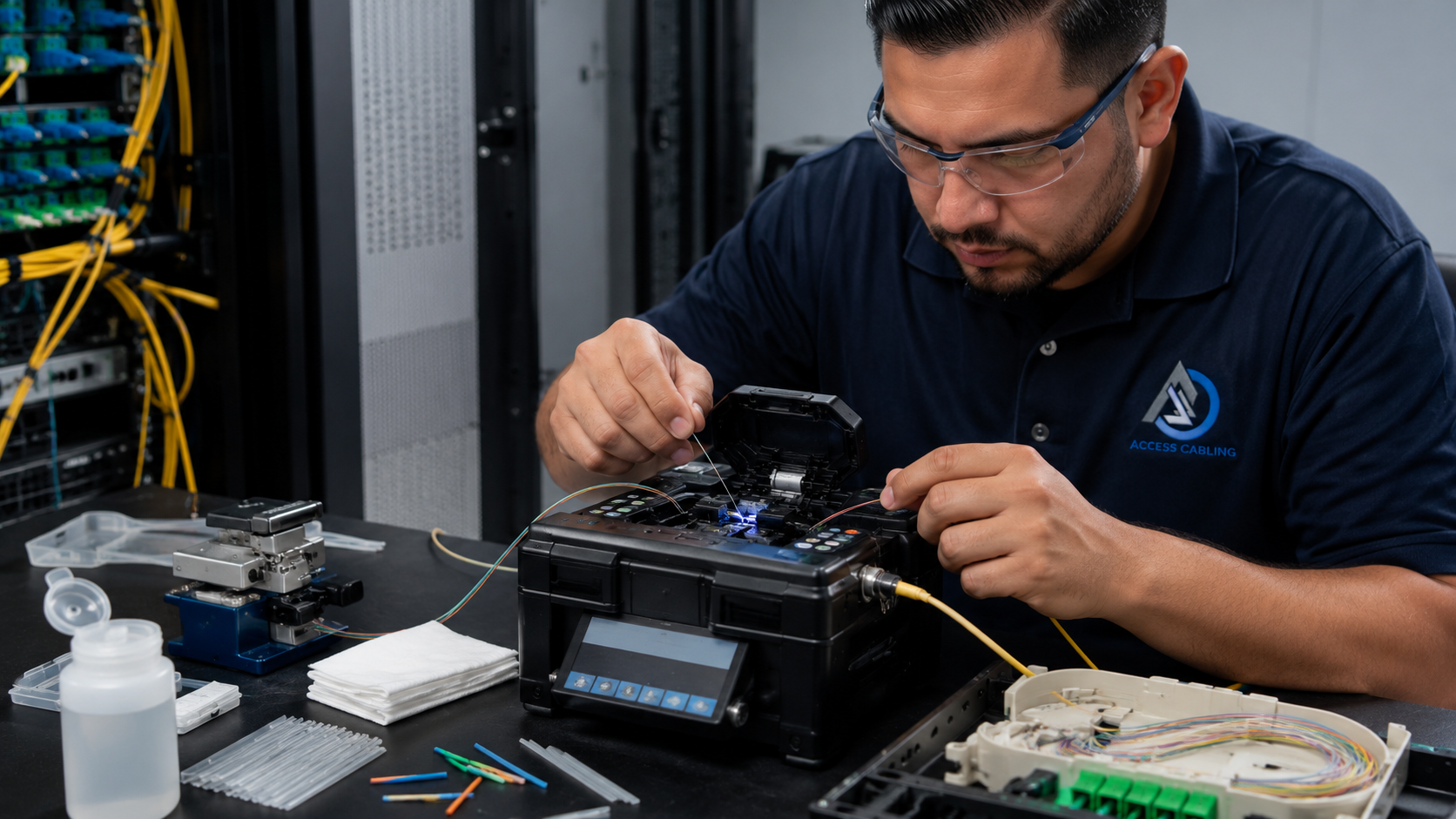
The installation of aerial fiber optic cable requires specialized equipment and trained personnel to ensure safe and compliant deployment. Our crews utilize bucket trucks, tensioning equipment, and lashing machines (e.g., GMP G2 Lashing Machines) to precisely attach fiber optic cables to messenger wires or directly to utility poles. Key installation steps include the proper pre-stringing of messenger wires at specified sag and tension, followed by the careful lashing of the fiber optic cable to the messenger. For ADSS cables, specialized gripping hardware and controlled tension pulling are employed to prevent jacket damage or exceeding the cable's maximum allowable tension (MAT) during installation, which could compromise its long-term performance. All pole attachments, including suspension clamps and dead-end grips, are applied according to manufacturer specifications and NESC clearance requirements to prevent cable abrasion or stress concentrations. Splice closures are then installed at designated locations, requiring meticulous fiber preparation, fusion splicing with high-precision fusion splicers (e.g., Fujikura, Sumitomo), and organized fiber routing within the closure trays. Throughout the installation, strict safety protocols, including grounding and bonding, are observed to protect both personnel and the integrity of existing utilities.
Comprehensive Testing, Certification & Documentation
Upon completion of aerial fiber optic installation, Access Cabling performs comprehensive testing and certification to guarantee performance and compliance. Our standard testing protocols include Optical Time Domain Reflectometer (OTDR) testing (e.g., Fluke OptiFiber Pro, EXFO FTB) from both ends of each fiber strand. This identifies splices, connectors, and any anomalies, providing an end-to-end attenuation signature. We also conduct Optical Loss Test Set (OLTS) / Power Meter and Light Source (PMLS) testing to measure true insertion loss (dB) across all fibers at 850nm, 1300nm (multimode), and 1310nm, 1550nm, 1625nm (singlemode), ensuring compliance with TIA/EIA-568-D limits. All test results are documented in detailed reports, typically in OPM, PDF, or .SOR formats, identifying pass/fail status and providing a baseline for future network troubleshooting. Additionally, visual inspections are performed to verify proper sag, attachment hardware, lashing wire integrity, and NESC clearances. Accurate 'as-built' documentation, including splice schematics, cable routing maps, and component inventories, is provided to the client for effective network management and future maintenance. This rigorous testing and documentation process is crucial for verifying the quality of the installation and ensuring the long-term reliability of the aerial fiber network.
Compliance, Safety & Environmental Considerations
Compliance and safety are paramount in aerial fiber optic deployments, given the inherent risks of working at heights and in proximity to energized power lines. Access Cabling strictly adheres to OSHA regulations for fall protection, electrical safety, and confined space entry when applicable. All technicians are trained and certified in NESC and local utility safety requirements. Environmental considerations also play a significant role. Our route planning minimizes impact on sensitive ecosystems where possible, and we ensure proper disposal of construction waste. We understand the permitting process required by various authorities having jurisdiction (AHJs), including local municipalities, county agencies, and utility companies for pole attachment agreements. Navigating 'make-ready' work – the process of adjusting existing utility attachments to accommodate new fiber – requires careful coordination with pole owners and often involves multiple stages of engineering review and approval. Our comprehensive approach ensures all regulatory hurdles are cleared, minimizing project delays and potential liabilities. Furthermore, we design with considerations for wildlife protection, employing stand-off brackets or bird guards where necessary to prevent damage to the cable plant and protect local fauna. This holistic approach ensures not just a compliant installation but one that is safely executed and environmentally responsible.
When to Choose Aerial Fiber: Use Cases and Advantages
Aerial fiber optic deployment is a strategic choice for a variety of applications where traditional underground trenching is either impractical, prohibitively expensive, or restricted. Common use cases include extending broadband networks to rural or remote areas where the cost per mile of trenching would be unsustainable. Universities and corporate campuses often utilize aerial fiber to connect buildings across expansive grounds, circumventing existing utilities or mature landscaping. Municipalities deploy it for smart city initiatives, connecting traffic signals, surveillance cameras, and public Wi-Fi access points. Utility companies leveraging existing pole infrastructure for SCADA systems or distributed sensor networks also benefit significantly. The primary advantages include faster deployment times compared to trenching, significantly lower civil works costs, and reduced disruption to existing infrastructure or ground surfaces. While vulnerable to environmental factors like high winds, ice storms, and vehicle strikes, modern armored cables and robust installation practices mitigate many of these risks. Aerial fiber provides a high-bandwidth, scalable solution, often serving as the backbone for last-mile connectivity where it intersects with buried or inside plant cabling.
Advanced OSP Project Management & Stakeholder Coordination
Successful aerial fiber deployment necessitates a highly specialized approach to Outside Plant (OSP) project management, distinct from trenching or in-building installations. This involves intricate coordination with a multitude of stakeholders, including municipal planning departments for right-of-way (ROW) permits and easements, utility pole owners (e.g., power companies, incumbent local exchange carriers - ILECs), governmental bodies like the FCC for regulatory compliance under Title II or Title VI considerations, and often, environmental protection agencies for land-use impact assessments. Our project management methodology integrates agile principles with critical path analysis (CPA) to manage complex dependencies and potential bottlenecks. This includes proactive engagement with pole owners to ascertain available Make Ready Engineering (MRE) capacity, negotiate pole attachment agreements (PAAs) adhering to NESC (National Electrical Safety Code) minimum clearances and loading requirements (e.g., NESC C2-2017 Part 2, Sections 23-26), and navigate dispute resolution processes. We employ advanced geospatial information systems (GIS) for route optimization, clash detection with existing overhead infrastructure (power lines, communication cables), and precise material staging. Communication protocols are established early, encompassing regular joint utility meetings, detailed progress reports accessible via secure online portals, and a structured change order management system to address unforeseen challenges like unexpected soil conditions impacting guy wire anchor points or new municipal aesthetic requirements. A key aspect is managing the logistics of specialized equipment, such as bucket trucks, tension stringing equipment, and optical time domain reflectometer (OTDR) calibration schedules, ensuring their availability aligns with permit windows and weather forecasts, thereby mitigating costly delays and ensuring efficient resource utilization across multiple simultaneous work fronts.
Mitigating Service Interruption: Cutover and Migration Strategies
Minimizing service interruption during the transition from legacy infrastructure or during network upgrades is paramount for aerial fiber projects. Access Cabling utilizes meticulously planned cutover and migration strategies to ensure near-zero downtime. This involves a multi-phase approach, beginning with detailed network audits of existing services and traffic patterns to identify critical circuits and peak usage periods. Our engineers then design redundant fiber paths where feasible, often employing diverse aerial routes or hybrid solutions incorporating underground segments to create a robust network architecture. For the cutover itself, we prioritize a 'hot-cut' methodology where new fiber services are activated and thoroughly tested while existing services remain operational. This necessitates careful planning of fiber splicing events, utilizing fusion splicers with sub-0.05dB insertion loss targets and OTDR verification on each spliced segment before transition. We leverage pre-connectorized aerial cable assemblies where applicable to expedite field deployment and reduce susceptibility to environmental contaminants during termination. The migration process incorporates a 'dark fiber' validation phase, ensuring the newly installed aerial fiber is fully tested for end-to-end optical continuity, attenuation (per TIA/EIA-568-C.3), return loss, and chromatic/polarization mode dispersion (PMD/CD) specifications prior to active equipment integration. Comprehensive MOPs (Method of Procedure) are developed for each cutover event, detailing every step, personnel assignments, communication matrix, and rollback procedures in case of unexpected anomalies. This includes coordination with end-user IT departments and service providers to schedule precise maintenance windows, conduct pre-migration data backups, and perform post-cutover performance monitoring and service level agreement (SLA) verification, guaranteeing a seamless transition for the client’s critical operations.
Common Failure Modes & Proactive Resilience Engineering
Aerial fiber infrastructure, while cost-effective and rapidly deployable, is uniquely susceptible to certain failure modes that demand specialized resilience engineering and proactive mitigation. Environmental factors represent a primary challenge; high winds can induce aeolian vibration causing fatigue on suspension hardware and fiber strands, while extreme temperatures lead to thermal expansion and contraction, potentially stressing buffer tubes and splice enclosures. Ice loading is another significant hazard, drastically increasing the weight on cables and poles, which can lead to catastrophic pole collapse or wire breakage (e.g., exceeding NESC Grade B loading criteria). Wildlife, particularly rodents and birds, can cause physical damage through gnawing or nest-building, impacting fiber integrity. Human factors, such as vehicle strikes on poles or accidental severing during adjacent construction activities, also contribute to outages. To counteract these vulnerabilities, Access Cabling employs a multi-faceted approach. We specify ADSS (All-Dielectric Self-Supporting) cables designed with high tensile strength (e.g., aramid yarns) and suitable sag-tension characteristics for the span lengths and environmental loads of the project, often referencing IEEE 1222 standards for optical fiber cable. Mid-span access points are carefully planned to minimize cable manipulation. Furthermore, physical hardening includes reinforced pole structures, strategically placed pole guards, and bright cable markers where vehicular encroachment is a risk. We utilize vibration dampeners (e.g., Stockbridge dampers) on long spans to mitigate galloping and static wire guards at attachment points. Regular preventative maintenance schedules include thermographic inspections for overheated terminations (though less common in passive aerial fiber, still relevant for powered enclosures) and visual pole integrity assessments. Fiber monitoring systems, such as Optical Network Monitors (ONM) or Distributed Acoustic Sensing (DAS), are deployed on critical routes, providing real-time alerts for fiber breaks, micro-bends, or unusual vibrations, enabling rapid fault localization and minimizing Mean Time To Repair (MTTR). This proactive engineering minimizes reactive repairs and enhances network uptime and longevity.
Sustainability and Life Cycle Cost Optimization (LCO)
The deployment of aerial fiber infrastructure offers significant sustainability advantages and opportunities for Life Cycle Cost Optimization (LCO) when compared to alternative methods. From an environmental perspective, aerial installation generally has a substantially lower carbon footprint than trenching, as it avoids disruptive excavation, minimizes soil disturbance, and reduces the fuel consumption and emissions associated with heavy digging machinery. This translates into less habitat destruction, reduced stormwater runoff and erosion, and lower requirements for landfill disposal of spoil. Access Cabling prioritizes the selection of fiber optic cables and associated hardware manufactured with responsible sourcing principles, including a focus on materials with lower embedded energy and increased recyclability at end-of-life. We also investigate cables utilizing smaller diameters and lighter weights, which further reduces the energy required for transportation and installation, as well as the structural load on utility poles. From an LCO standpoint, aerial fiber offers faster deployment times, translating to quicker revenue realization and reduced labor costs compared to the extensive earthworks and restoration often required for underground installations. While aerial infrastructure is exposed to environmental elements, careful material selection – such as UV-stabilized polymeric components for enclosures and robust jacket materials with high abrasion resistance – significantly extends the operational lifespan, deferring replacement costs. Proactive maintenance strategies, as outlined previously, prevent catastrophic failures and their associated emergency repair expenses. Furthermore, the inherent accessibility of aerial fiber facilitates easier upgrades and modifications, reducing future intervention costs compared to buried ducts, which might require re-excavation. Our LCO models incorporate initial capital expenditure, ongoing operational expenses (maintenance, power for potential active equipment), projected repair costs based on failure rates, and end-of-life considerations, providing clients with a holistic financial forecast and demonstrating the long-term value and environmental responsibility of aerial fiber solutions.