
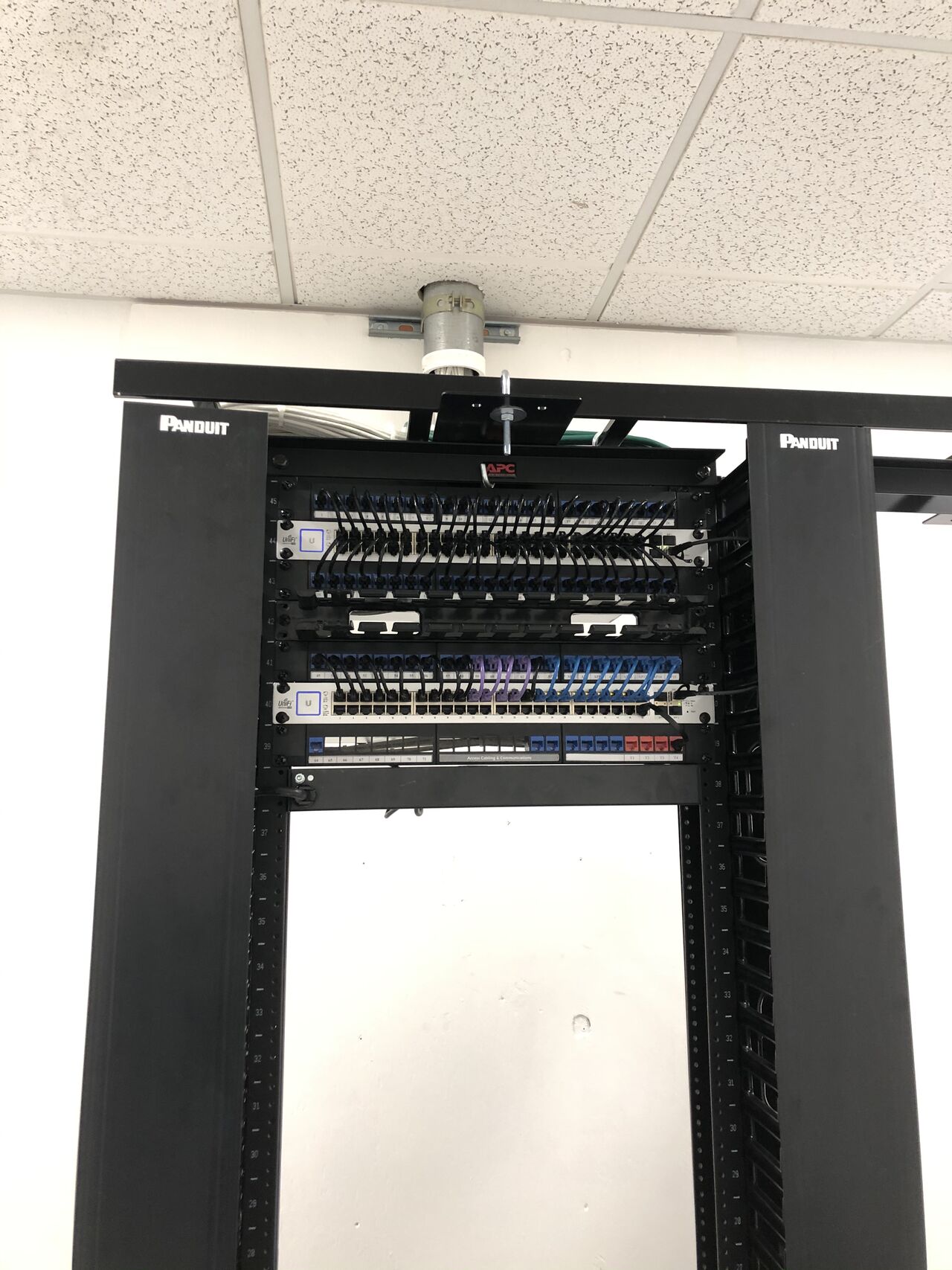
MDF and IDF layout is the invisible design decision that determines whether a building ages gracefully. Get it right and every floor has clean horizontal runs, room for growth, and predictable troubleshooting. Get it wrong and every MAC visit becomes a wall opening.
- One MDF per building; one IDF per 10,000–15,000 sq ft or per floor.
- IDF footprint must accommodate racks, cooling, and future expansion.
- Backbone: OS2 or OM4, 30% strand growth allowance.
- Bonding and grounding per TIA-607, not per electrician judgment.
Executive summary
A proper MDF/IDF layout uses star topology with one MDF per building and IDFs positioned so that every work-area outlet is within 90 m of an IDF. Each IDF is sized for its expected drop count plus 30% growth, has ducted or split cooling adequate for the switch load, and is bonded to the building grounding electrode system per TIA-607.
Why bad IDF placement hurts
An IDF that serves a 100 m radius from a corner of the floor forces horizontal runs that exceed 90 m to the far side. Every device beyond 90 m becomes a fiber conversion, a repeater, or a new IDF later. Placing the IDF centrally at design time prevents years of retrofit.
Design principles
- IDF centered geometrically on the floor's outlet population.
- Room size: minimum 8×10 ft for a 200-drop floor; larger for multi-tenant.
- Cooling: ducted split or dedicated CRAC; 350–500 W per sq ft baseline.
- Power: dedicated 20A circuit per rack; UPS with 15 min runtime minimum.
- Pathway: ladder rack into the top of every rack.
- Backbone: at least 12 strands OM4 or OS2 per IDF, terminated on LC or MTP.
Common mistakes
- Cabling closet doubling as janitor storage — no cooling, no security.
- IDF at the corner of the floor forcing long horizontal runs.
- No dedicated cooling — switch throttles or fails in summer.
- Missing ground bar — bonding is ad-hoc.
Best practices
- IDF placement driven by outlet centroid, not by architectural convenience.
- Dedicated cooling and UPS.
- Card-access with logging.
- TGB installed and bonded per TIA-607.
- As-built rack elevation posted inside the door.
Reference IDF build
| Element | Spec |
|---|---|
| Racks | 1–2 × 45U 4-post open frame |
| Power | Dedicated 20A per rack, UPS 3–6 kVA |
| Cooling | Ducted split or dedicated CRAC |
| Backbone | 12–24 strands OM4/OS2 to MDF |
| Ground | TGB bonded to TBB and TMGB |
| Security | Card-access, camera, door sensor |
When to call a professional
MDF/IDF placement should be settled in the schematic-design phase of any commercial project. Architects who set closet placement without a low-voltage consultant regularly locate telecom rooms in corners or against exterior walls, both of which cause problems later.